The structure of a Fanuc 0M series CNC machine is based on a modular architecture where a central control unit coordinates with various peripheral units, drive systems, and the operator interface. The interconnection between these components is achieved through specialized physical connectors, high-speed serial links, and grounding systems designed to ensure electrical stability and noise resistance.
1. Core Control Unit Architecture
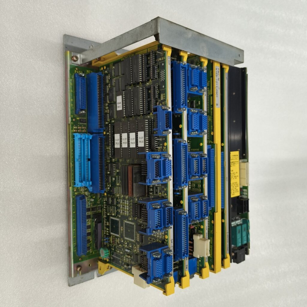
The “brain” of the Fanuc 0M is the Control Unit, which consists of a Master Printed Circuit Board (PCB) that serves as the base for several plug-in cards and modules. The specific configuration depends on the model (e.g., 0-MC, 0-MD) and optional functions.
- Master PCB: Houses the central processor and provides slots for specialized functional cards.
- Memory Card: Stores part programs, system parameters, and offset data in CMOS memory, which is preserved by a battery backup unit.
- Axis Control Cards: Manage the movement of controlled axes (typically 1–4, with expansion for 5–8 axes). They translate CNC commands into signals for the servo amplifiers and process position/velocity feedback.
- Internal I/O Cards: Provide the standard interface for machine signals (DI/DO), available in various types (C5, C6, C7, E1, E2, E3) depending on the required number of input/output points.
- PMC (Programmable Machine Controller): Manages the sequence control of the machine tool, handling signals between the CNC and the machine’s electrical cabinet.
2. Power Supply and Input Units
The Power Supply Unit (PSU) is typically mounted directly onto the Master PCB.
- Function: It converts AC input (200–240V) into various DC voltages (+5V, +15V, -15V, +24V) required by the control unit and peripheral devices like the CRT.
- Input Unit: Often built into the PSU (PSU AI type), it includes an AC service outlet for auxiliary components like fan motors and manages the power ON/OFF sequence through external switch signals.
3. Operator Interface
The operator station serves as the human-machine interface (HMI).
- CRT/MDI Unit: Consists of the display screen and a keyboard for data entry. It connects to the control unit via a Video Signal Interface (Type A for CRT/PDP or Type B for LCD) and a dedicated keyboard signal cable.
- Machine Operator’s Panel: Features keys for manual machine operation, emergency stop, and override switches. It connects to the CNC through the I/O interface, often using encoded signals to reduce the total number of required wires.
4. Motion Control System Interconnection
The motion system involves complex interconnections between the control unit and the machine’s mechanical axes.
- Servo Interface: The CNC sends axis commands (e.g., PWM signals) to Digital Servo Amplifiers, which drive the AC Servo Motors.
- Feedback Loops: Position and velocity data are sent back to the CNC from Pulse Coders (built into the motors or mounted separately). Depending on the loop type (semi-closed or closed), feedback is routed either to the axis card or through the amplifier.
- Spindle Interface: Spindle control can be Analog (via a command voltage) or Digital/Serial (via optical fiber or high-speed serial links).
5. Communication and Expansion Links
For expanded functionality and connectivity:
- FANUC I/O Link: A high-speed serial interface that allows the master CNC to control multiple slave units, such as I/O Unit-Model A or additional operator panels, significantly expanding the available DI/DO points.
- Peripheral Interfaces: Dedicated connectors (M5, M74, M77) provide RS-232-C or RS-422 interfaces for external devices like tape readers, PCs for drip-feeding (DNC), or floppy cassette adapters.
- Manual Pulse Generator (MPG): Handwheels for manual axis jogging connect via a specialized interface providing a 5V power supply and A/B phase signals.
6. Grounding and Noise Management
Correct interconnection requires a strictly defined Grounding System to prevent electrical noise from causing malfunctions:
- Signal Ground (SG): Reference voltage for electronic signals.
- Frame Ground (FG): Safety ground connecting cases, panels, and cable shields.
- System Ground: Connects all individual unit grounds to the main machine ground.
- Cabling: Signals are separated into groups (AC power vs. low-voltage DI/DO vs. high-speed feedback) and kept at least 10cm apart to avoid electromagnetic induction.


