Introduction
In the world of Computer Numerical Control (CNC) machining, the controller is the brain the single component that translates human intent into precise, repeatable mechanical motion. Among the controllers that have shaped modern manufacturing, Mitsubishi Electric’s MELDAS C64 stands as a landmark achievement. Launched in the early 2000s as part of the MELDAS C6/C64 series, it brought high-speed processing, multi-axis coordination, and deeply integrated PLC capabilities to machine tools across turning, milling, and assembly applications.
This post dissects the MELDAS C64 from the ground up: its physical hardware, the internal architecture that coordinates motion, the servo and spindle drive ecosystem it commands, the programming environment that makes it tick, and the communication fabric that ties it all together. Whether you’re a maintenance technician troubleshooting an alarm, a machine builder evaluating a control platform, or simply a manufacturing enthusiast curious about how a CNC controller actually works, this anatomy guide is for you.
1. Historical Context: Where the C64 Fits
Mitsubishi Electric has been a fixture in CNC technology since the 1950s, progressively developing the MELDAS (Mitsubishi Electric Digital Automatic System) family through several generations. The lineage runs roughly as follows:
- MELDAS 50/500 Series : Entry and mid-range controllers from the 1990s, widely deployed on lathes and machining centers.
- MELDAS 60/60S Series : High-performance controllers for complex multi-axis machines, including 5-axis simultaneous machining.
- MELDAS C6/C64 Series : Introduced around 2000–2001, targeting assembly lines, networked production cells, and machines requiring high-speed, high-accuracy control with flexible PLC integration.
- MELDAS C70 / M800 / M80 Series : The successors, incorporating faster processors, larger displays, and deeper IoT connectivity.
The C64 was designed to bridge the gap between the feature-rich MELDAS 60 and the more cost-sensitive MELDAS 50. It offered many of the advanced motion control algorithms found in the 60 series such as high-speed cycle processing, fine interpolation, and advanced look-ahead in a more compact, modular package suited to production-line integration.
The “C64” designation distinguishes it from the base “C6” variant. The C64 supports additional axes, higher processing throughput, and extended PLC capabilities, making it the premium offering within the C6/C64 family.
2. System Configuration Overview
A MELDAS C64 CNC system is not a single box. It is a modular assembly of discrete units, each responsible for a specific function. Understanding the system configuration is the first step in understanding the anatomy.
The major components are:
- CNC Control Unit (CPU Unit) : The central processing module.
- Display Unit : The operator interface (LCD or CRT panel).
- Operation Panel / Keyboard : Physical buttons, switches, and input devices.
- Servo Amplifier Units : Drive electronics for each servo axis.
- Spindle Amplifier Unit : Drive electronics for the spindle motor(s).
- Servo Motors and Spindle Motor : The electromechanical actuators.
- Stabilized Power Supply Unit : Provides regulated DC power to the amplifier bus.
- PLC (Programmable Logic Controller) Module : Integrated or external ladder-logic controller for machine-side I/O.
- I/O Units : Discrete and analog input/output modules connected to sensors, relays, valves, and other machine peripherals.
- Communication Modules : Interfaces for Ethernet, serial, and fieldbus networks.
These units are connected via a combination of dedicated high-speed serial links (for servo/spindle communication), a backplane bus (for internal data exchange), and standard industrial wiring (for power, I/O, and safety circuits).
3. The CNC Control Unit: The Brain
3.1 CPU and Processing Architecture
At the heart of the MELDAS C64 is a dedicated CPU board that executes three interleaved processing loops:
- Interpolation Cycle : The finest time-slice, typically running at 0.5ms to 2ms. This cycle computes the incremental position command for each axis every tick, converting the programmed tool path (G-code blocks) into a stream of position set points. The C64’s fine interpolation engine supports nanometer-level resolution on linear axes and sub-arc-second resolution on rotary axes.
- Servo Control Cycle : Runs at the same or a harmonic multiple of the interpolation cycle. Each axis’s servo loop reads the encoder feedback, computes the position error, runs the velocity and current loop (PI/PID control), and outputs a torque command to the servo amplifier. The C64 supports advanced feed-forward control, where the velocity and acceleration of upcoming moves are pre-computed and injected into the servo loop, dramatically reducing following error during high-speed contouring.
- PLC Scan Cycle : Typically 4ms to 8ms, this cycle executes the user-defined ladder logic program that manages machine-side sequencing: tool changes, pallet handling, coolant control, safety interlocks, and operator panel logic.
The C64’s CPU was designed for deterministic real-time execution. Unlike general-purpose computers, where interrupt latency and task scheduling can introduce jitter, the C64’s hardware and firmware guarantee that the interpolation and servo cycles complete within their allocated windows a property known as hard real-time. This determinism is what allows the controller to maintain smooth, accurate motion even during complex multi-axis contouring.
3.2 Memory Architecture
The C64 employs a multi-tier memory architecture:
- ROM / Flash Memory : Stores the CNC system firmware (the operating system, interpolation kernel, and built-in macro programs). This is non-volatile and factory-programmed.
- SRAM with Battery Backup : Holds machine parameters, tool offset data, work coordinate systems, pitch error compensation tables, and the user PLC program. A lithium battery maintains this memory during power-off, and a low-battery alarm warns the operator before data loss occurs.
- DRAM : Provides working memory for the CNC part program buffer, look-ahead buffer, and runtime data structures. The C64 can store and execute large part programs, with the look-ahead buffer typically holding 200 or more blocks of upcoming tool path, enabling the interpolation engine to plan smooth acceleration profiles across corners and short segments.
3.3 Servo Bus and Communication
The CNC control unit communicates with the servo and spindle amplifiers via a high-speed serial servo bus. This dedicated link transmits position commands from the interpolator to each amplifier and returns encoder feedback and diagnostic data in the opposite direction all within each servo cycle tick.
The servo bus topology is typically a daisy-chain (series connection) from the CNC unit through the first servo amplifier, then the second, and so on, terminating at the spindle amplifier. Each amplifier in the chain has a unique axis address assigned by parameter. The serial bus uses a proprietary protocol optimized for low latency and high noise immunity, essential in the electrically noisy environment of a machine tool.
4. Servo and Spindle Drive System
4.1 Servo Amplifiers
The MELDAS C64 is typically paired with Mitsubishi’s MDS-series servo amplifiers (such as the MDS-B-V1/V2 or MDS-C1-V1 series). Each servo amplifier is a current-regulated inverter that converts the DC bus voltage into three-phase AC waveforms to drive a permanent-magnet synchronous servo motor.
Key characteristics of the servo drive chain:
- Current Loop Bandwidth : Typically 1 kHz or higher, enabling rapid torque response for tight contouring.
- Velocity Loop Bandwidth : 200–500 Hz, providing stable speed regulation under varying load conditions.
- Position Loop Gain : Configurable via CNC parameters, typically ranging from 30 to 100 (1/s) depending on the mechanical stiffness of the machine.
- Absolute Position Encoders : The C64 system typically uses absolute encoders (serial communication type) on each axis, eliminating the need for reference-point return after power-on. The encoder battery on the amplifier maintains position memory during power-off.
Each servo amplifier connects to the DC bus supplied by the stabilized power supply unit. The power supply rectifies incoming three-phase AC mains into a regulated DC link voltage (typically 300–340 VDC), with regenerative braking energy dissipated through a regenerative resistor or, in more advanced configurations, fed back to the mains via a regenerative converter.
4.2 Spindle Amplifier
The spindle amplifier drives the main spindle motor typically a high-torque induction motor or, in higher-performance applications, a permanent-magnet synchronous spindle motor. The spindle amplifier receives speed commands (RPM setpoints) and orientation commands (for tool change positioning) from the CNC unit.
The C64 supports:
- Constant Surface Speed (G96) : Automatically adjusts spindle RPM based on the current cutting diameter to maintain a constant surface speed, improving finish quality on turning operations.
- Spindle Orientation : Precise angular positioning of the spindle for automatic tool change, typically using a proximity sensor or encoder marker pulse.
- Rigid Tapping : Synchronizes the spindle rotation with the Z-axis feed to cut threads without a floating tap holder, requiring tight real-time coordination between the spindle and the tapping axis.
4.3 Servo Motors
Mitsubishi’s HF-series and HA-series servo motors are the standard pairing for the C64. These are permanent-magnet AC servo motors with low inertia (for rapid acceleration), high torque density, and integrated absolute encoders. Motor sizes range from small units (50W, for auxiliary axes like tailstock quills) to large units (several kW, for heavy cutting axis on machining centers).
5. The PLC: Machine-Side Intelligence
One of the MELDAS C64’s distinguishing features is its deeply integrated PLC subsystem. Unlike external PLCs that communicate with the CNC via slow fieldbus links, the C64’s PLC is tightly coupled to the CNC kernel, sharing memory and running within the same real-time framework.
5.1 Ladder Logic Programming
The PLC is programmed using ladder diagram (LD) language, developed and debugged using Mitsubishi’s MELSOFT GX Developer (or the earlier MEDOC) software environment. The ladder program reads discrete inputs (sensors, switches, operator buttons), executes conditional and sequential logic, and drives discrete outputs (solenoids, indicator lights, relay coils).
The PLC also provides a rich set of CNC-specific function blocks:
– M-code handling : Detecting and executing auxiliary functions called by the part program (e.g., M03 for spindle start, M06 for tool change).
– Axis control commands : Initiating manual axis movements from the PLC, such as pallet indexing or tailstock advance.
– Alarm and message display : Triggering CNC alarm messages or operator guidance text on the display from within the ladder logic.
– Data register access : Reading and writing CNC system variables, macro variables, and tool data from the PLC program, enabling adaptive machining strategies.
5.2 DDB (Direct Data Bus) Interface
The C6/C64 introduced the DDB (Direct Data Bus) function, a high-bandwidth memory-mapped interface that allows the user PLC program to exchange data with the CNC kernel in real time. Through DDB, the PLC can read axis positions, feed rates, spindle loads, and cycle states with minimal latency enabling applications like:
- Real-time load monitoring and adaptive feed rate control
- Synchronized multi-PLC coordination in multi-channel configurations
- High-speed data logging of process variables for quality traceability
6. Operator Interface: Display and Operation Panel
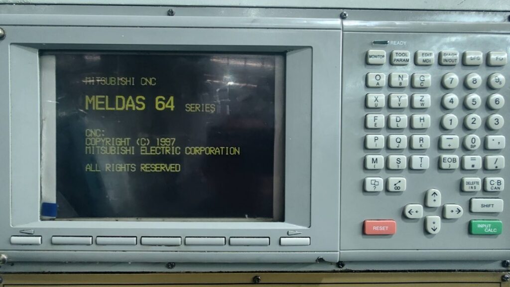
6.1 Display Unit
The MELDAS C64 supports a range of display units, from compact 8.4-inch LCD panels to larger 10.4-inch and 15-inch displays. The display provides:
- Program display and editing : Viewing and modifying part programs on-screen.
- Real-time position monitoring : Machine coordinates, work coordinates, remaining distance, and servo load for each axis.
- Alarm and diagnostic screens : Detailed alarm codes, alarm history, PLC diagnostics, and servo status.
- Parameter screens : Access to the hundreds of CNC parameters that configure machine behavior (feed limits, acceleration profiles, backlash compensation, etc.).
- Graphical tool path display : A 2D or 3D wireframe simulation of the programmed tool path, useful for verifying programs before cutting.
The display unit connects to the CNC control unit via a dedicated video and communication cable. In some machine configurations, a GOT (Graphic Operation Terminal) from Mitsubishi’s GOT1000 series is used as the display, providing a touchscreen interface and the ability to simultaneously monitor both the CNC and the PLC on a single panel.
6.2 Operation Panel
The physical operation panel includes:
- Mode select switches : JOG, HANDLE, MDI, MEMORY, EDIT, and other operating modes.
- Feed rate and spindle speed override knobs : Analog potentiometers allowing the operator to scale programmed feed rates and spindle speeds in real time (typically 0–200%).
- Cycle start and feed hold buttons : Green and yellow buttons that initiate and pause automatic program execution.
- Axis select and jog buttons : For manual axis movement in JOG mode.
- Emergency stop button : A mushroom-head button that immediately cuts servo power and halts all motion via a hardwired safety circuit.
7. Software Features and Advanced Capabilities
7.1 High-Speed Processing
The C64 implements what Mitsubishi calls “high-speed processing mode” a firmware-level optimization that reduces the block processing time (the time to compute one interpolation segment) to sub-millisecond levels. This is critical for high-speed machining of complex 3D contours (like die and mold surfaces), where the part program may contain thousands of short linear segments. Without fast block processing, the machine would be unable to maintain programmed feed rates, resulting in hesitation, surface marks, and increased cycle times.
7.2 Look-Ahead and Cornering
The C64’s look-ahead buffer scans upcoming blocks in the part program, computing the deceleration required to negotiate corners, small radii, and direction changes. By planning velocity profiles across multiple blocks rather than reacting block-by-block, the controller maintains higher average feed rates while respecting the machine’s acceleration limits and the programmed tolerance.
7.3 NURBS and Smooth Interpolation
For die and mold applications, the C64 supports NURBS (Non-Uniform Rational B-Spline) interpolation and smooth interpolation functions. These allow the CAM system to send spline curves directly to the CNC, which then interpolates them at high resolution internally eliminating the polygonal approximation errors inherent in sending thousands of short linear segments.
7.4 Pitch Error Compensation and Backlash Compensation
The C64 provides software-based compensation for mechanical imperfections:
- Pitch error compensation : A table of position corrections, measured by laser interferometer that the CNC applies at each encoder position to compensate for lead-screw pitch errors.
- Backlash compensation : A fixed offset applied when an axis reverses direction, compensating for mechanical play in the ball nut, bearings, or gear train.
7.5 Multi-Part System and Work Offsets
For production-line applications, the C64 supports multiple work coordinate systems (G54–G59 and extended offsets), enabling machining of multiple parts in a single setup or fixture. Combined with sub-program calls and macro programming, this allows compact, efficient part programs for high-volume production.
8. Communication and Networking
The MELDAS C64 was designed with factory networking in mind. Communication options include:
- Ethernet : For program transfer, remote monitoring, and integration with CAM systems and shop-floor management software.
- Serial (RS-232C) : A legacy but still widely used interface for program transfer and DNC (Direct Numerical Control) drip-feeding.
- CC-Link : Mitsubishi’s proprietary industrial fieldbus, enabling the CNC to communicate with Mitsubishi PLCs (MELSEC series), HMI panels, and remote I/O stations at high speed.
- USB : Later configurations added USB ports for program transfer via thumb drives.
These communication capabilities allow the C64 to function as a node in a networked production environment, feeding cycle-time data, alarm logs, and production counts to centralized monitoring systems.
9. Maintenance and Diagnostics
The MELDAS C64 includes a comprehensive diagnostic framework:
- Alarm system : Multi-level alarms (operator, machine, servo, PLC) with detailed codes and descriptions, guiding the technician to the root cause.
- Servo tuning tools : Built-in screens for monitoring servo error, current, and gain margins, enabling on-machine tuning without external oscilloscopes.
- PLC diagnostics : Real-time monitoring of I/O states, timer/counter values, and internal relay states, accessible from the display unit.
- Self-diagnosis : The CNC performs power-on self-tests, checking memory integrity, encoder communication, and amplifier status before enabling motion.
For maintenance, the Connection and Maintenance Manual (document number BNP-B2255) provides detailed procedures for component replacement, cable specifications, connector pinouts, and shield grounding requirements essential reference for any workshop keeping a C64-equipped machine running.
10. Real-World Applications
The MELDAS C64 found its home on a wide variety of machine tools:
- CNC Lathes (Turning Centers) : 2-axis and multi-axis lathes with live tooling, C-axis spindle positioning, and sub-spindle synchronization.
- Machining Centers : 3-axis and 4-axis vertical/horizontal machining centers with automatic tool changers.
- Assembly Machines : High-speed pick-and-place and press-fit systems in automotive and electronics production lines, where the C64’s PLC integration and network capabilities were particularly valued.
- Grinding Machines : Cylindrical and surface grinders requiring precise spindle speed control and in-process gauging integration.
- Transfer Lines : Multi-station production lines where multiple C64 controllers coordinated via CC-Link, each managing a single machining station within the line.
Conclusion
The Mitsubishi MELDAS C64 is more than a CNC controller it is a complete motion control ecosystem. From the real-time interpolation kernel that generates sub-millisecond position commands, through the servo amplifier chain that converts those commands into precisely controlled torque, to the integrated PLC that orchestrates the machine’s peripheral systems, every layer of the C64’s architecture was designed with a single goal: to turn raw material into finished parts with speed, accuracy, and reliability.
For the maintenance technician, understanding the C64’s anatomy means understanding where to look when things go wrong whether that’s a servo alarm pointing to an encoder fault, a PLC diagnostic screen revealing a stuck sensor, or a parameter misconfiguration causing poor surface finish. For the machine builder, it means understanding the tools available for optimizing a machine’s performance from servo tuning to look-ahead configuration to communication integration.
The MELDAS C64 may no longer be Mitsubishi’s flagship CNC that honor now belongs to the M800 and M8V series but thousands of C64-equipped machines remain in productive service around the world, a testament to the robustness of their design. Understanding their anatomy is not just an academic exercise; it’s a practical necessity for the manufacturing professionals who keep these machines running.
References:
Mitsubishi Electric MELDAS C6/C64 Specifications Manual (BNP-B2266),
Connection and Maintenance Manual (BNP-B2255),
Instruction Manual (BNP-B2259),
PLC Programming Manual (BNP-B2309),
DDB Interface Manual (BNP-B2312).


