In the world of precision manufacturing, Computer Numerical Control (CNC) machining stands as the pinnacle of accuracy and repeatability. A CNC machining center can cut complex geometries into hard metals with tolerances measured in microns. However, this incredible capability relies on a fundamental concept that is often overlooked by beginners but mastered by experts: the coordinate system. Specifically, the management of reference points.
Without clearly defined reference points, a CNC machine is effectively blind. It possesses the power to move at high speeds and the torque to cut steel, but it has no inherent knowledge of where the cutting tool is in relation to the raw material. The entire language of G-code is built upon the assumption that the controller knows exactly where “Zero” is.
This blog post will delve deep into the hierarchy of reference points on a CNC machining center. We will explore the difference between Machine Zero and Work Zero, the mechanics of homing, the critical nature of tool length offsets, and the best practices for ensuring that your reference points remain accurate throughout a production run. Understanding these concepts is not just about programming; it is about safety, efficiency, and part quality.
The Foundation: The Cartesian Coordinate System
Before dissecting specific reference points, we must briefly establish the framework in which they exist. CNC machining centers operate on a three-dimensional Cartesian coordinate system. This consists of three linear axes: X, Y, and Z.
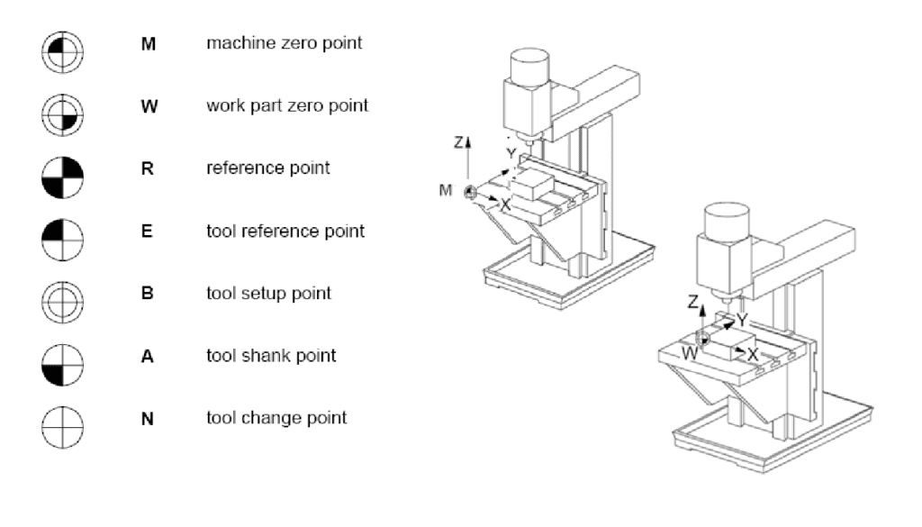
- The X-axis typically represents the longest travel of the machine table (left to right).
- The Y-axis represents the depth (front to back).
- The Z-axis represents the vertical movement (up and down), usually associated with the spindle.
These axes follow the “Right-Hand Rule.” If you point your right thumb in the positive direction of the X-axis and your index finger in the positive direction of the Y-axis, your middle finger will point in the positive direction of the Z-axis.
Every movement command in a CNC program (e.g., G01 X10.0 Y5.0 Z-2.0) tells the machine to move to a specific location within this grid. But where does the grid begin? This is where reference points become critical. There are two primary coordinate systems at play: the Machine Coordinate System (MCS) and the Work Coordinate System (WCS). Confusing these two is the leading cause of crashes and scrapped parts in machine shops.
Machine Zero: The Physical Home
The first and most immutable reference point is Machine Zero, often referred to as Machine Home or the Origin. This point is physically defined by the machine tool builder. It is the “true” zero of the CNC controller.
Defining Machine Zero
On a vertical machining center (VMC), Machine Zero is typically located at the extreme positive limits of the X, Y, and Z axes. When the machine is “homed,” the spindle nose moves to the furthest right, furthest back, and highest up position possible within the work envelope.
It is crucial to understand that Machine Zero is fixed. You, the operator or programmer, cannot change it. It is hard-coded into the machine’s parameters and physically aligned with limit switches or encoder markers during manufacturing.
The Homing Procedure
When a CNC machine is powered on, it does not know where it is. The motors may have moved slightly due to gravity or residual vibration while the power was off. Therefore, the first operation after a power-up must be a Reference Point Return, commonly known as “Homing.”
During the homing cycle, each axis moves slowly toward its limit switch or encoder marker. Once the switch is triggered, the machine knows it has reached the physical boundary. It then backs off slightly and searches for a precise “grid mark” or “pulse” from the servo motor encoder. Once this pulse is found, the controller resets the position register for that axis to the predefined Machine Zero coordinates (often X0, Y0, Z0 in the machine coordinate system, though some builders set Z0 at the spindle nose and X/Y at the center of the table).
Absolute vs. Incremental Encoders
The necessity of homing every day depends on the type of feedback system the machine uses.
- Incremental Encoders: These systems count pulses to determine movement. If power is lost, the count is lost. Machines with incremental encoders must be homed every time they are turned on to re-establish the Machine Zero reference.
- Absolute Encoders: These systems have a unique code for every position, maintained by a battery backup. Even if power is lost, the machine “knows” where it is. While homing is not strictly required for position knowledge on these machines, it is still best practice to perform a reference return to synchronize the software display with the physical reality and clear any drift errors.
Why Machine Zero Matters
Programmers rarely write code based directly on Machine Zero. However, Machine Zero is the anchor for everything else. All Work Offsets are calculated as a distance from Machine Zero. If the homing sequence fails or is interrupted, the Machine Zero reference is lost, and consequently, all Work Offsets become invalid. Attempting to run a program without a valid Machine Zero reference is a guaranteed recipe for a catastrophic crash.
Work Zero: The Programmer’s Reality
If Machine Zero is the physical reality of the steel and iron of the machine, Work Zero (or Part Zero) is the logical reality of the part being manufactured. This is the most important reference point for the CNC programmer and the setup machinist.
The Concept of Work Offsets
Imagine you have a block of aluminum clamped in a vise on the machine table. The corner of that block is not at Machine Zero. It might be at X200, Y150, Z-100 relative to the machine home. Programming every coordinate relative to Machine Zero would be a nightmare. Every time you moved the vise, you would have to rewrite the entire program.
To solve this, CNC controllers allow us to create Work Coordinate Systems (WCS). We tell the controller: “Treat this specific corner of the part as X0, Y0, Z0.” The controller then mathematically shifts all program coordinates to align with this new origin.
These offsets are accessed via G-codes, most commonly G54 through G59.
- G54: Primary work offset.
- G55-G59: Secondary work offsets.
Setting the Work Zero
Setting the Work Zero is the core responsibility of the setup machinist. It involves determining the distance from Machine Zero to the desired Part Zero.
- X and Y Axis: Typically, the operator will use an edge finder or a 3D probe to touch off the sides of the part. If the part is 100mm wide and the edge finder touches the left side, the operator calculates the center or sets the corner to zero depending on the print requirements. This value is entered into the G54 offset register.
- Z Axis: This is often the most critical setting. The Z-zero is usually the top surface of the finished part. The operator might use a Z-axis setter (a puck of known height) or touch off a tool to the top of the stock.
Multiple Work Offsets in One Setup
One of the greatest advantages of understanding reference points is the ability to machine multiple parts in one setup.
- Scenario: You have a large table and need to machine four identical brackets.
- Solution: You clamp all four brackets. You set G54 for the first bracket, G55 for the second, G56 for the third, and G57 for the fourth.
- Program: Your G-code calls
G54to machine the first part, thenG55to machine the second, without changing the program coordinates. The machine simply shifts the reference point for each cycle.
This flexibility highlights why Work Zero is superior to Machine Zero for programming. It decouples the part geometry from the machine’s physical location, allowing for modular fixturing and efficient batch production.
Tool Length Offsets: The Z-Axis Reference
While Work Offsets handle the location of the part, Tool Length Offsets (TLO) handle the location of the cutter. This is a distinct reference point that often confuses novices.
The Gauge Line Concept
The CNC controller controls the position of the spindle nose, not the tip of the cutting tool. However, the program coordinates are written assuming the cut happens at the tool tip.
- Tool A might be 50mm long.
- Tool B might be 100mm long.
If the machine moves the spindle nose to Z-10.0, Tool A will cut 10mm deep, but Tool B will cut 60mm deep (crashing into the part). To compensate, we use Tool Length Offsets (usually H-codes, e.g., H01, H02).
Establishing the Tool Reference
There are two common methods for managing this reference:
- Gauge Line Method: All tools are measured relative to a theoretical line on the spindle (the gauge line). The offset value is the distance from the tool tip to this line. This is common in high-production environments with preset tooling.
- Master Tool Method: One tool (usually the longest or a specific probe) is designated as the “master” with an offset of zero. All other tools are measured relative to the master tool. If Tool 2 is 10mm shorter than the master, its offset is -10.0.
The Interaction of Work Z and Tool Offsets
The final Z-position of the tool tip is a calculation:Final Z = Machine Z Position + Work Offset (G54 Z) + Tool Length Offset (H)
If your Work Zero is set on the top of the part, and your Tool Length Offset is accurate, the command G01 Z0.0 will gently touch the tool tip to the top of the part. If either reference point is incorrect, the tool will either air-cut above the part or dig into the vise below it.
Reference Point Return Commands (G28)
In CNC programming, you will frequently encounter the command G28. This is the “Return to Reference Point” command. It is vital for safety and tool changes.
How G28 Works
The syntax is usually G91 G28 Z0.0 (in incremental mode) or G28 X0.0 Y0.0 Z0.0.
When executed, the machine moves the specified axes to the Machine Zero position.
Crucial Safety Note: G28 often moves through an intermediate point.
If you command G28 X0.0 Y0.0, the machine does not necessarily go straight home. It first moves to the current X0, Y0 position (in the active coordinate system), and then goes to Machine Home.
- Risk: If your Work Zero is set near a clamp, and you command G28, the machine might move to the Work Zero coordinate first, potentially dragging the tool through the clamp before heading home.
- Best Practice: Always clear the part before calling G28. A safe sequence is:
G00 Z100.0(Retract tool high)G91 G28 Z0.0(Send Z to home via intermediate current pos)G28 X0.0 Y0.0(Send X/Y to home)
Why Use G28?
- Tool Changes: Most machining centers require the spindle to be at a specific Z-height (often Machine Zero) to allow the tool changer arm to rotate without hitting the table or fixtures.
- Pallet Changers: If the machine has an automatic pallet changer, the table must return to a specific reference point to swap fixtures safely.
- Resetting Errors: After a crash or an emergency stop, returning to the reference point re-synchronizes the axis position displays.
Rotary Axes and 4th/5th Axis Reference Points
Modern machining centers often include rotary axes (A, B, or C). These introduce a layer of complexity regarding reference points.
The Center of Rotation
On a linear axis, Zero is a plane. On a rotary axis, Zero is a vector line. The critical reference point for a 4th axis is the Center of Rotation.
- If you are machining a cylinder, your X and Y work offsets must account for the height and lateral position of the rotary axis centerline.
- If the rotary table is not calibrated correctly, the part will be machined off-center as it rotates.
Homing Rotary Axes
Rotary axes also require homing. However, because they rotate 360 degrees, the “Home” position is arbitrary but must be consistent. Usually, the home position is defined as 0 degrees.
- Unwind Feature: Some controllers have an “unwind” feature. If a program rotates the C-axis 720 degrees (two full spins), the machine might physically wind up the cabling. A reference point return ensures the axis resets to the 0-degree mechanical stop to prevent cable damage.
Common Errors and Troubleshooting Reference Points
Even experienced machinists can make mistakes with reference points. Here are the most common pitfalls and how to avoid them.
1. The “Walking” Part
Problem: You set your Work Zero at the start of a shift. After machining 50 parts, the 51st part is out of tolerance.
Cause: The fixture or vise may have shifted slightly due to cutting forces or thermal expansion. The Machine Zero is stable, but the Work Zero has moved relative to the machine.
Solution: Implement in-process probing. Use a probe to check a datum feature on the part every 10 cycles and automatically update the Work Offset if drift is detected.
2. Incorrect Tool Length Offset Entry
Problem: The machine crashes into the part on the first Z-axis move.
Cause: The Tool Length Offset was measured incorrectly, or the wrong H-code was called in the program (e.g., calling H05 when Tool 5 is loaded, but H05 contains the offset for a drill, not an end mill).
Solution: Verify offsets on the control screen before running. Use a “dry run” with the spindle disabled and the Z-axis offset increased (e.g., +10mm) to simulate the cut safely above the part.
3. Confusing G53 and G54
Problem: The machine moves to an unexpected location.
Cause: G54 is the modal Work Offset. G53 is the command to move in the Machine Coordinate System temporarily. If a programmer accidentally leaves a G53 active or misunderstands the modal state, the machine ignores the Work Offset.
Solution: Always explicitly call the work offset at the beginning of the program (e.g., G54 G90 G17). Never assume the machine remembers the previous operator’s offset.
4. Z-Axis Setter Height Errors
Problem: All parts are consistently 0.5mm too deep or too shallow.
Cause: The Z-axis setter puck used to set the Work Zero has a specific height (e.g., 50.00mm). If the operator enters the wrong height into the calculator or uses a worn/damaged puck, the Z-reference will be shifted.
Solution: Calibrate Z-axis setters regularly. Treat them as precision measuring instruments, not shop tools.
Best Practices for Managing Reference Points
To ensure longevity of your machine and quality of your parts, adopt these standard operating procedures:
- Home Every Morning: Even if you have absolute encoders, home the machine at the start of the shift. It warms up the ball screws and verifies the limit switches are functional.
- Document Your Fixturing: When setting a Work Offset, write down the location of the vise or fixture relative to the table T-slots. If you need to remove and reinstall the fixture later, you can approximate the location before fine-tuning the offset.
- Use Tool Presetters: If possible, measure tool lengths offline on a presetter. This reduces machine downtime and removes the risk of crashing a tool while trying to measure it inside the work envelope.
- Verify Offsets Before Cycle Start: Make it a habit to look at the offset page. Check that the G54 Z-value makes sense (e.g., it shouldn’t be 500mm away from the table if the part is right in front of you).
- Understand Your Controller: Fanuc, Haas, Siemens, and Heidenhain all handle reference points slightly differently. Read the specific parameter manual for your machine. For example, some machines allow “Second Reference Points” for specific tool change positions that are not Machine Home.
The Future of Reference Points: Automation and Probing
As manufacturing moves towards Industry 4.0, the manual setting of reference points is becoming automated.
Touch Probes: Renishaw and Blum probes allow the machine to find its own reference points. The probe can touch the part surfaces, calculate the center, and update the G54 offset automatically. This removes human error from the equation.
Laser Tool Setters: Instead of manually setting tool lengths, the tool is broken across a laser beam inside the machine. The controller measures the exact length and wear, updating the TLO in real-time.
Workpiece Setting Systems: Devices like the “3D Sensor” allow the operator to place a part on the table, press a button, and have the machine map the part’s orientation and position, effectively creating a digital twin of the setup before a single chip is cut.
Despite this automation, the underlying principles remain the same. The machine still needs to know where Machine Zero is to calibrate the probe. The probe still needs to calculate a Work Offset to tell the cutter where to go. The technology changes, but the geometry does not.
Conclusion
Reference points are the invisible grid upon which all CNC machining is built. They are the bridge between the digital world of CAD/CAM and the physical world of steel and cutting tools.
Mastering reference points requires a clear mental distinction between the Machine Coordinate System (the machine’s reality) and the Work Coordinate System (the part’s reality). It requires discipline in setting Tool Length Offsets and a rigorous adherence to safety protocols when using Reference Point Return commands like G28.
When these points are managed correctly, the CNC machining center becomes a tool of infinite possibility, capable of reproducing complex geometries with unwavering consistency. When they are misunderstood, they become the source of costly crashes and scrapped material.
For the aspiring machinist or programmer, investing time to understand these concepts is the highest-return activity you can undertake. It transforms you from a button-pusher into a manufacturing engineer who understands the soul of the machine. Respect the Zero, verify your offsets, and always know where your tool is in space. In the precision world of CNC, knowing your reference points is the difference between success and failure.


