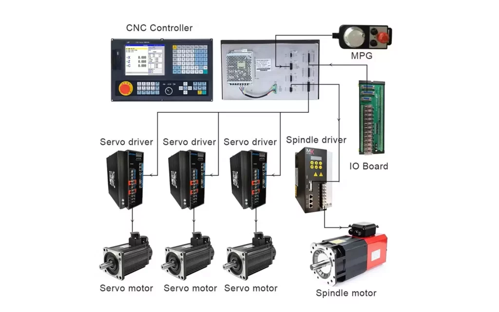
The Computerized numerical control system is the heart of any CNC machine. Below, we will focus specifically on the control part of a CNC machine, and describe its structure and how it interacts with other components.
Computerized numerical control system structure
1. CNC Controller
- Function: The FANUC controller processes the input program (G-code or proprietary FANUC language) and translates it into precise commands for the machine’s axes, spindle, and auxiliary functions.
- Structure:
- CPU Module: The central processing unit that executes the program instructions.
- Memory Modules: Stores the program data, tool offsets, workpiece coordinates, and operational parameters.
- ROM: Contains the firmware and system software.
- RAM: Temporary storage for active programs and variables.
- Input/Output Interfaces:
- Ethernet Port: For communication with external devices (e.g., computers, DNC systems).
- Serial Ports: For connecting to older devices like tape readers or printers.
- Digital I/Os: Connects to motors, sensors, and actuators.
- Display Unit: A touchscreen interface for programming, monitoring, and diagnostics.
- Key Switches: Allows the operator to switch between manual, automatic, and editing modes.
2. Program Execution
- Function: The controller reads and executes the CNC program step by step, controlling the movement of the machine’s axes and the operation of the spindle.
- Example Program:
GcodeO0001 (Sample Program)G90 G00 X0 Y0 Z50 (Rapid move to starting position)G01 Z-10 F100 (Linear interpolation, plunge to Z=-10 at feed rate 100 mm/min)G01 X50 Y50 (Linear interpolation to new position)G00 Z50 (Rapid retract)M30 (End of program) - Interaction:
- The controller reads each line of the program and interprets the G-codes and M-codes.
- For example,
G00triggers rapid movement, whileG01initiates linear interpolation at a specified feed rate (F100). - The controller sends signals to the drive system to move the axes (
X,Y,Z) to the specified positions.
3. Axis Control
- Function: The controller manages the motion of each axis independently or in coordination with others.
- Structure:
- Axis Modules: Dedicated hardware modules for each axis (e.g., X, Y, Z, A, B, C).
- Servo Amplifiers: Power the servo motors for precise control of axis movement.
- Interaction:
- The controller calculates the required motion based on the program and sends commands to the servo amplifiers.
- For example, in the line
G01 X50 Y50, the controller synchronizes the movement of the X and Y axes to ensure smooth diagonal motion.
4. Spindle Control
- Function: The controller regulates the speed and direction of the spindle motor.
- Structure:
- Spindle Amplifier: Controls the spindle motor’s speed and torque.
- Encoder Feedback: Provides real-time feedback on the spindle’s rotational speed and position.
- Interaction:
- In the line
M03 S2000, the controller activates the spindle motor (M03) and sets its speed to 2000 RPM (S2000). - The encoder ensures that the spindle maintains the desired speed, and the controller adjusts the power supplied to the motor if necessary.
- In the line
5. Feedback System
- Function: Ensures accurate positioning by providing real-time feedback to the controller about the actual position of the axes and spindle.
- Structure:
- Encoders: Attached to the servo motors or ball screws to measure rotational or linear position.
- Resolvers: Used in some systems for high-precision spindle feedback.
- Interaction:
- During motion, the encoders continuously send position data back to the controller.
- If there is a discrepancy between the commanded position and the actual position, the controller adjusts the motor commands to correct the error.
6. Auxiliary Functions
- Function: The controller manages auxiliary functions such as coolant, tool changes, and pallet changers.
- Structure:
- I/O Modules: Interface with external devices like pumps, valves, and tool changers.
- Interaction:
- For example, the line
M08activates the coolant pump, whileM09turns it off. - Tool changes are initiated with
M06, and the controller communicates with the tool changer to execute the swap.
- For example, the line
7. User Interface
- Function: Allows the operator to interact with the controller, load programs, monitor status, and make adjustments.
- Structure:
- Touchscreen Display: Shows the current program, machine status, alarms, and diagnostic information.
- MDI (Manual Data Input) Panel: Allows the operator to enter commands manually.
- Emergency Stop Button: Halts all machine operations immediately.
- Interaction:
- The operator can use the touchscreen to load a program from internal memory or an external source.
- During operation, the display shows the current position of the axes, spindle speed, and feed rate.
8. Error Handling and Diagnostics
- Function: The controller includes advanced error detection and diagnostic capabilities to identify and resolve issues.
- Structure:
- Alarm Codes: Specific codes for different types of errors (e.g., overtravel, overheating, loss of synchronization).
- Diagnostics Menu: Provides detailed information about the machine’s status and potential problems.
- Interaction:
- If an error occurs (e.g., overtravel), the controller stops the machine and displays an alarm code (e.g.,
ALM 401for X-axis overtravel). - The operator can use the diagnostics menu to investigate the cause and take corrective action.
- If an error occurs (e.g., overtravel), the controller stops the machine and displays an alarm code (e.g.,
Example Interaction of a Computerized numerical control system:
- The operator loads a CNC program into the controller via the touchscreen interface.
- The controller interprets the program and sends commands to the drive system for axis movement and the spindle amplifier for spindle control.
- Encoders provide real-time feedback to ensure precise positioning and speed control.
- Auxiliary functions like coolant activation (
M08) and tool changes (M06) are executed as needed. - If an error occurs, the controller halts the machine, displays an alarm code, and allows the operator to diagnose and resolve the issue.
This coordinated interaction between the controller and the machine’s various components enables highly precise and automated manufacturing processes.
Computerized Numerical Control (CNC) Systems: Fanuc, Sinumerik, and Heidenhain
CNC controls like Fanuc, Siemens Sinumerik, and Heidenhain are industry leaders, differing in hardware design, software interfaces, and integration capabilities. Below is a breakdown of their physical components, structure, and interactions, with examples for each brand.
1. Fanuc CNC Control System
Key Components
- CNC Unit (Main Controller):
- Physical Example: Fanuc 31i/32i/30i Mate or Fanuc 30i MB control units.
- Function: Houses the microprocessor, memory, and I/O modules. Processes G-code/M-code, performs interpolation, and manages motor control.
- Input/Output Devices:
- Fanuc CNC Pendant (MDI/CRT Unit): Touchscreen interface for program editing and monitoring.
- USB/Network Interface: For loading programs from external PCs.
- Drive System:
- Motors: Fanuc Alpha i Series servo motors (e.g., Alfa-i αi-H).
- Drivers/Amplifiers: Fanuc αi-H servo amplifiers, which convert CNC signals to motor commands.
- Feedback Systems:
- Encoders: Fanuc Sercos III absolute encoders for real-time position feedback.
- User Interface:
- Fanuc CNC Screen (LCD/Touchscreen): Displays toolpaths, diagnostics, and alarms.
Interaction Workflow (Example)
- Program Upload: A G-code file (e.g.,
G01 X10 Y5 F100) is loaded via USB or network. - Parsing: The Fanuc CNC Unit interprets the code, calculates interpolated paths, and sends commands to the αi-H amplifiers.
- Motor Activation: Amplifiers send high-current signals to αi-H servo motors, driving the X/Y axes via ballscrews.
- Feedback Loop: Sercos encoders monitor motor position/speed, sending data back to the CNC unit for adjustments.
- Monitoring: The operator views progress on the Fanuc pendant and troubleshoots via alarm codes.
2. Siemens Sinumerik CNC System
Key Components
- CNC Unit:
- Physical Example: Sinumerik 840D sl or Sinumerik 828D control units.
- Function: Integrates PLC (Programmable Logic Controller) for complex automation tasks.
- Input/Output Devices:
- Sinumerik Operate Panel: Touchscreen interface with intuitive HMI (Human-Machine Interface).
- PC Interface: Connects via OPC UA or Profinet for CAD/CAM integration.
- Drive System:
- Motors: Siemens 1FT5/1FT6 servo motors.
- Drivers: Siemens 6SL3342 inverter modules.
- Feedback Systems:
- Encoders: Sinumerik Linear Encoders (e.g., Siemens SITRANS LMT series).
- User Interface:
- Sinumerik HMI: Supports multilingual displays and NC (Numerical Control) parameter adjustments.
Interaction Workflow (Example)
- Program Upload: A CAD/CAM-generated NC program is loaded via Sinumerik Operate.
- PLC Integration: The 840D sl CNC unit coordinates PLC logic for tool changes and spindle control.
- Motion Control: The CNC sends interpolated commands to 1FT6 motors via Profinet for synchronized multi-axis movement.
- Closed-Loop Feedback: Encoders provide real-time data to the CNC, ensuring ±0.001 mm accuracy.
- Monitoring: The operator uses Sinumerik Operate to adjust parameters (e.g., feed rate) during machining.
3. Heidenhain CNC System

Key Components
- CNC Unit:
- Physical Example: TNC 415 or iTNC 530 control units.
- Function: Uses Heidenhain synchro technology for precise interpolation.
- Input/Output Devices:
- Heidenhain Multitasking Terminal: Color touchscreen with ISO 13399 tool database support.
- USB/Network Ports: For program transfer.
- Drive System:
- Motors: Heidenhain brushless servo motors (e.g., TSK series).
- Drivers: Heidenhain HSC bus-compatible amplifiers.
- Feedback Systems:
- Encoders: Heidenhain linear scales (e.g., LS 290 series) for high-precision positioning.
- User Interface:
- Heidenhain HSC Software: Advanced diagnostics and simulation tools.
Interaction Workflow (Example)
- Program Upload: A G-code file is loaded into the TNC 640 via USB.
- Interpolation: The CNC unit calculates paths using Heidenhain’s synchro technology.
- Motor Control: Commands are sent to TSK motors via HSC bus, enabling high-torque, low-inertia motion.
- Feedback Loop: LS 290 scales monitor position, ensuring accuracy within microns.
- Monitoring: The operator uses the Multitasking Terminal to view 3D simulations and adjust tool offsets.
Critical Differences Between Brands
| Feature | Fanuc | Sinumerik | Heidenhain |
|---|---|---|---|
| Primary Strength | Parametric programming | PLC integration | High-precision encoders |
| Networking | Fanuc Field Bus | Profinet/OPC UA | HSC bus |
| User Interface | MDI/CRT pendant | Sinumerik Operate | Multitasking Terminal |
| Encoder Tech | Sercos III | Siemens SITRANS | Linear scales (LS 290) |
 Computerized numerical control system used in DIY project

BREAKOUT BOARD
Takes signals from computer and breaks them out to individual terminals.
Usually include:
- I/O with Opto-isolation
- Relays
- VFD control (0-10V)
- Interfaces
- Parallel
- most popular / widest support
- USB
- Not much hardware available
- Timing issues
- Ethernet
- Growing support
- Parallel

Summary
- Fanuc excels in robustness and parametric flexibility.
- Sinumerik integrates advanced PLC automation for complex workflows.
- Heidenhain prioritizes precision with proprietary encoder systems.
Each system’s components interact to achieve closed-loop control, ensuring accuracy in machining tasks, from simple drilling to 5-axis milling.


