In the complex world of Computer Numerical Control (CNC) machining, precision and repeatability are the hallmarks of a master engineer. As electromechanical professionals, we understand that a machine is only as reliable as its reference points. While most entry-level programmers are familiar with G28 (Return to Machine Zero), the G30 command (Return to Secondary Reference Position) is a powerful tool for optimizing cycle times and enhancing workshop safety.
This post explores the technical nuances of the G30 command, its implementation in modern automation, and how it serves as a cornerstone for maintaining production efficiency in mechanical manufacturing workshops.
Understanding the CNC Reference Landscape
Before diving into G30, we must establish the hierarchy of coordinate systems that govern a CNC machine.
1. Machine Zero (Machine Reference Point)
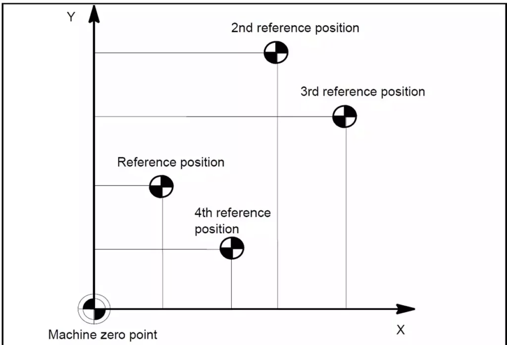
The Machine Zero point (often designated as M) is the absolute physical limit of the machine’s travel. It is typically established during the “homing” procedure when the machine is first powered on. This point is immutable and serves as the foundation for all other coordinates.
2. Work Zero (Part Zero)
Work Zero (W) is the point on the specific workpiece from which all dimensions in the part program are calculated. Using codes like G54 through G59, we shift the machine’s focus from its physical limits to the actual part being machined.
3. The Secondary Reference Position (G30)
While G28 returns the tool to the primary machine zero, G30 directs the machine to a predefined secondary reference point. This point is defined in the machine’s parameters (often Parameter 1241 in Fanuc-compatible controls).
The Technical Mechanics of G30
G30 is a non-modal preparatory function that typically involves an intermediate point to ensure a safe tool path. The standard syntax is:
G30 P2 X__ Y__ Z__
- P2: Specifies the second reference point. (P3 and P4 can also be used for 3rd and 4th reference positions if the controller supports them).
- X, Y, Z: These coordinates represent an intermediate point the tool must pass through before reaching the reference position.
The Intermediate Point Logic
Just like G28, the G30 command is often executed in two steps:
- Move to the intermediate point: The tool moves at a rapid traverse rate (G00) to the X, Y, and Z coordinates specified in the G30 block.+1
- Move to the reference point: From that intermediate location, the machine then moves directly to the stored secondary reference position.
Pro-Tip for Maintenance: Always use incremental coordinates (G91) for the intermediate point when executing a G30 to avoid unexpected “dog-leg” movements that could cause a crash. For example: G91 G30 P2 Z0 will move the Z-axis directly to the secondary reference point without any horizontal deviation.+1
Why Use G30 Instead of G28?
In a high-volume manufacturing workshop, every second saved is profit earned. G30 offers three primary advantages:
1. Optimized Tool Change Positions
Standard machine zero (G28) is often at the furthest reaches of the machine’s travel. If your workpiece is small and your tool changer is located closer to the table, returning all the way to G28 for every tool change is a waste of time. G30 allows you to set a tool change position just inches away from the work zone, significantly reducing non-cutting time.
2. Avoiding Obstacles
In complex setups with tall fixtures or rotary tables, a straight path to machine zero might result in a collision. By defining a G30 position that clears these obstacles, you can automate a safe “escape route” for the cutting tool after a machining cycle.
3. Support for Automated Loading
For workshops utilizing robotic arms for part loading/unloading, G30 provides a consistent “handshake” position. The robot knows exactly where the table or spindle will be, ensuring the automation remains synchronized without needing to travel to the machine’s absolute limits.
Programming Example: Milling a Component
Consider a scenario where we are milling an aluminum part and need to change tools. Instead of returning to the far-off machine home, we will use G30 to move to a convenient tool-change height.
G-Code
(PART: HOUSING_01)
N10 G90 G20 G17 (Absolute, Inch, XY Plane)
N20 G54 G00 X1.0 Y1.0 (Move to start position)
N30 S2500 M03 (Spindle On)
... (Machining Operation)
N100 G91 G30 P2 Z0 (Rapid to 2nd Ref Point in Z only)
N110 M06 T02 (Change to Tool 2 at the G30 position)
N120 G90 (Back to Absolute mode)
...
In this example, G91 G30 P2 Z0 ensures the spindle retracts to a safe, pre-set height for the Automatic Tool Changer (ATC) without moving the X or Y axes, which keeps the tool directly above the next entry point.
Maintenance and Workshop Safety
As an engineer managing a production unit, maintaining “good working order” means ensuring these parameters are correctly calibrated.
- Parameter Verification: Periodically check that the G30 coordinates stored in the MCU (Machine Control Unit) haven’t been altered during maintenance or by unauthorized personnel.+1
- Sensor Health: The reference positions rely on limit switches or absolute encoders. Ensure these are clean and free of metal chips to prevent “drift” in your reference points.
- Simulation: Before running a program with a new G30 position, use the machine’s graphic display or dry-run mode to verify the tool path. This is a critical step in preventing catastrophic machine crashes.+2
Conclusion
The G30 “Return to Secondary Reference Position” is more than just a line of code; it is a strategic tool for the modern electromechanical engineer. By mastering its use, you can reduce wear on machine ball screws by minimizing unnecessary travel, decrease cycle times, and create a safer, more automated environment for your manufacturing workshop.
Properly implemented, G30 ensures that your production units remain efficient, accurate, and most importantly in perfect working order.


