
If you’ve ever stood over a CNC lathe, manually touching off a tool against a part surface or a piece of paper, you know the struggle. It’s time-consuming, prone to human error, and frankly, a bit nerve-wracking when you’re inching a carbide insert toward a spinning chuck.
In the modern machine shop, time is money, and accuracy is everything. This is where the Lathe Tool Setter comes in.
Whether you are a shop owner looking to reduce downtime or a machinist wanting to streamline your setup, understanding and utilizing a tool setter is a game-changer. In this post, we’ll break down what a lathe tool setter is, why you need one, and how to get the most out of it.
What is a Lathe Tool Setter?
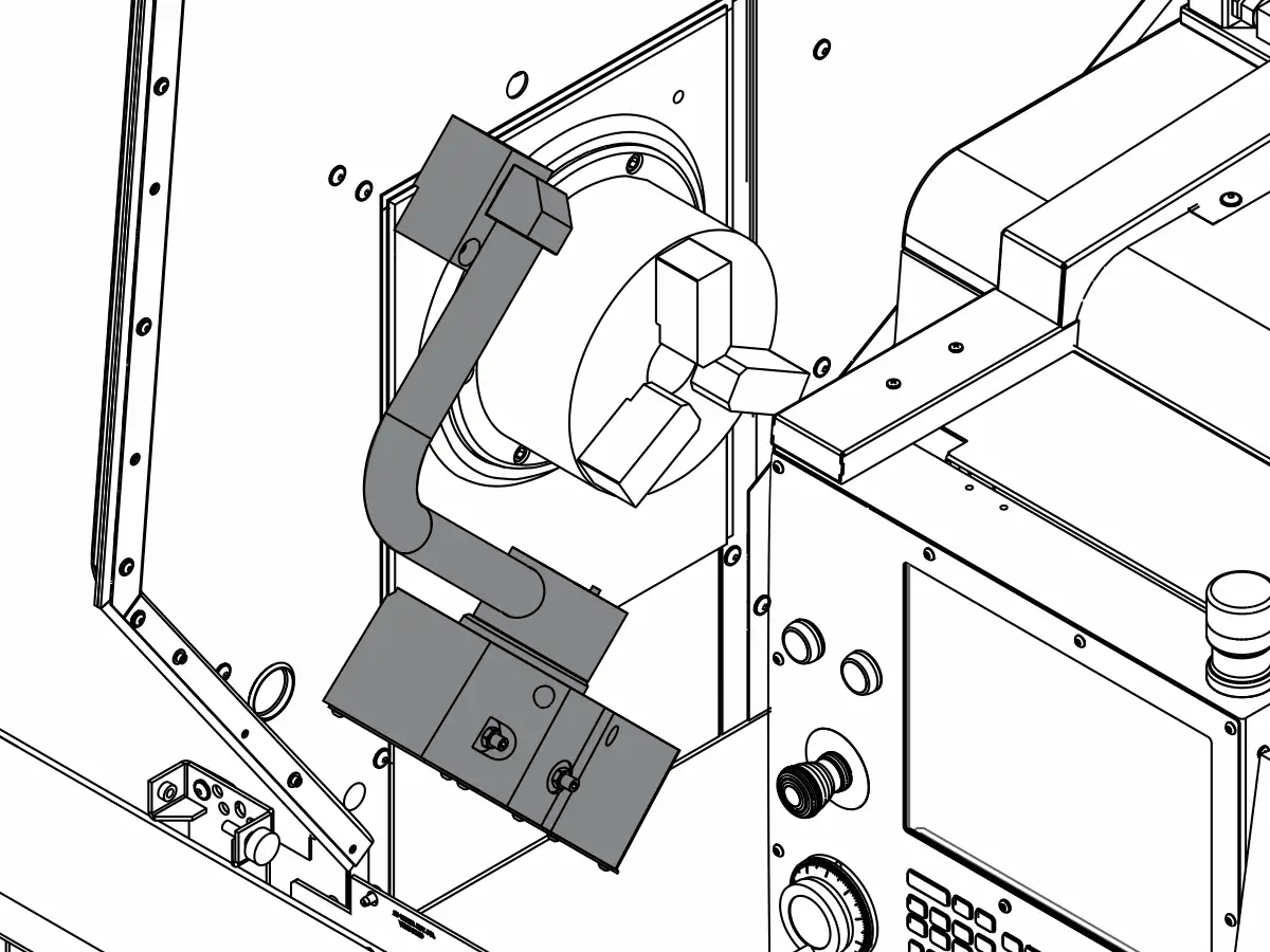
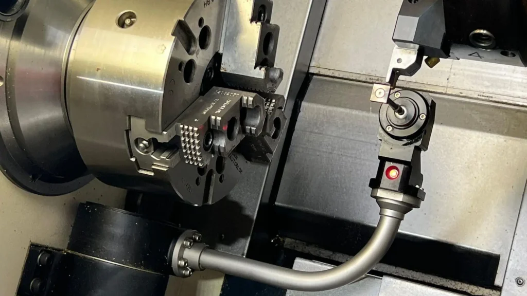
A lathe tool setter (often called a tool setting probe or touch-off probe) is a precision device mounted directly onto the machine bed or turret of a CNC lathe.
Its primary function is to automatically measure the position of the cutting tool relative to the machine’s zero point. When the tool tip physically touches the probe’s surface, a signal is sent to the CNC control unit. The control then calculates the exact tool offset (both X and Z axes) and updates the tool table automatically.
The 4 Major Benefits of Using a Tool Setter
Why should you invest in this accessory? Here are the four pillars of value:
1. Drastically Reduced Setup Time
Manual tool setting can take 10 to 20 minutes per tool, depending on the operator’s skill. A tool setter reduces this to seconds. For jobs with multiple tools or high-mix/low-volume production, this adds up to hours of saved machine time per week.
2. Improved Accuracy and Consistency
Human touch varies. One operator might set a tool slightly differently than another. A tool setter removes the “feel” from the equation. It provides repeatable accuracy down to the micron, ensuring that the first part off the machine is good, and the 100th part is identical.
3. Enhanced Safety
Manual setting often requires the operator to place their hands near the chuck and the tool turret while in jog mode. With an automated tool setter, the operator can stand clear while the machine performs the measurement cycle, reducing the risk of injury.
4. Reduced Scrap and Crash Risk
Incorrect tool offsets are a leading cause of crashes and scrap parts. By automating the offset measurement, you eliminate data entry errors and miscalculations. Additionally, many tool setters can detect if a tool is broken or worn beyond a certain limit before the cutting cycle even begins.
How Does It Work?
The process is surprisingly simple and integrates directly with your CNC control (such as Fanuc, Haas, or Siemens).
- Mounting: The setter is secured to a predefined location on the machine.
- Calibration: The machine is calibrated to know the exact position of the setter itself.
- Measurement Cycle: The operator calls up a macro program. The turret moves the tool toward the probe.
- Contact: When the tool tip touches the probe surface, the probe triggers.
- Offset Update: The CNC control records the machine coordinates at the moment of contact and automatically writes the geometry offset into the tool table.
Types of Lathe Tool Setters
While the goal is the same, there are a few variations you might encounter:
- Touch-Off Probes: The most common type. Uses a physical contact surface (often a hardened steel pad) that triggers a switch. Reliable and cost-effective.
- Laser Tool Setters: A laser beam is projected across the work area. When the tool breaks the beam, the position is recorded. These are non-contact and incredibly fast but are more expensive and require a clean environment (chips can interfere with the laser).
- Workpiece Probing vs. Tool Setting: Don’t confuse the two! A workpiece probe measures the part. A tool setter measures the tool. Many shops use both for a fully automated cell.
Best Practices for Using a Tool Setter
To ensure your tool setter lasts and provides accurate data, follow these tips:
- Keep it Clean: Chips and coolant buildup on the probe surface will cause false readings. Blow it off before every use.
- Don’t Crash It: The tool setter is a precision instrument. If you crash a tool into it at high speed, you can damage the internal mechanism. Use slow feed rates during the setting cycle.
- Regular Calibration: Periodically verify the setter’s position using a master tool or a ring gauge to ensure it hasn’t shifted.
- Check Tool Condition: Remember, a tool setter measures position, not quality. It won’t tell you if the insert is chipped, only where the tip is. Always visually inspect inserts.
TOOL SETTER OPERATES PROCEDURE
Lathe with FANUC OT command
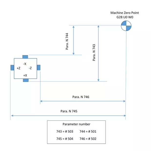
Tool sensor distance setting
Macro variables definition and description
| MACRO NO | DESCRIPTION |
| #100 | TOOL NUMBER |
| #101 | ABSOLUTE VALUE FOR #108 |
| #102 | ABSOLUTE VALUE FOR #109 |
| #103 | X- AXIS GEOMETRRY/OFFSET AMOUT (2700) TOOL NUMBER |
| #104 | Z- AXIS GEOMETRRY/OFFSET AMOUT (2800) TOOL NUMBER |
| #108 | X-AXIS TOOL BREAKGE AMOUNT (GEOMETRY VALUE) |
| #109 | Z-AXIS TOOL BREAKGE AMOUNT (GEOMETRY VALUE) |
| #111 | X-AXIS DIRECTION G00 PAUSE STOP POSITION (#123) |
| #112 | Z-AXIS DIRECTION G00 PAUSE STOP POSITION (#124) |
| #113 | X-AXIS SKIP BLOCK MEASURED VALUE |
| #114 | Z-AXIS SKIP BLOCK MEASURED VALUE |
| #128 | CALL G STATUS VALUE (05 GROUP) |
| #129 | CALL G50 WORK POINT X-VALUE |
| #130 | CALL GS0 WORK POINT Z-VALUE |
| #131 | TOOL NUMBER |
| #500 | G31 SKIP SIGNAL DISTANCE. |
| #501 | THE DISTANCE FOR FROM ZRN TO -X PLUNGER OF SENSOR |
| #502 | THE DISTANCE FOR FROM ZRN TO -Z PLUNGER OF SENSOR |
| #503 | THE DISTANCE FOR FROM ZRN TO +X PLUNGER OF SENSOR |
| #504 | THE DISTANCE FOR FROM ZRN TO +Z PLUNGER OF SENSOR |
| #505 | BREAKGE VALUE |
Program selection
macro programs
Program O9001
- 09001
- G65 H01 P#128 Q#4005
- G98
- G28 U0
- G28 W0
- G65 H02 P#129 Q#5001 R#5121
- G65 H02 P#130 Q#5002 R#5122
- G50 X-#5121 Z-#5122
- M43
- G65 H24 P#131 Q#1032
- G65 H12 P#100 Q#131 R15
- G65 H02 P#103 Q#100 R2700
- G65 H02 P#104 Q#100 R2800
- G65 H03 P#112 Q#502 R20.
- G00 Z#112
- G65 H02 P#111 Q#501 R6.
- G00 X#111
- G04 X1.
- G65 H03 P#113 Q#501 R#500
- G31 X#113 F100
- G65 H03 P#101 Q#5061 R#501
- G65 H01 P#108 Q#101
- G65 H22 P#101 Q#101
- G65 H83 P100 Q#101 R#505
- G65 H02 P#108 Q#108 R#9103
- G65 H01 P#9103 Q#108
- G00 U30.
- W30.
- G65 H03 P#123 Q#501 R40.
- G65 H02 P#124 Q#502 R2.5
- G00 X#123
- Z#124
- G65 H03 P#114 Q#502 R#500
- G31 Z#114 F100
- G65 H03 P#102 Q#5062 R#502
- G65 H01 P#109 Q#102
- G65 H22 P#102 Q#102
- G65 H83 P110 Q#102 R#505
- G65 H02 P#109 Q#109 R#9104
- G65 H01 P#9104 Q#109
- G00 W50.
- G28 U0
- G28 W0
- G65 H80 P150
- N100 G28 U0
- G28 W0
- M44
- G04 X10
- G#128
- G50 X#129 Z#130
- G65 H99 P1
- N110 G00 W50.
- G28 U0
- G28 W0
- M44
- G04 X10
- G#128
- G50 X#129 Z#130
- G65 H99 P11
- N150 T00
- M44
- G04 X10
- G#128
- G50 X#129 Z#130
- M99
Here is a detailed explanation of each line in the macro program for measuring tool gauges using a CNC lathe tool setter:
| Line | Code / Command | Explanation |
|---|---|---|
| 1 | %09001 | Program number. Identifies this as program 09001 in the machine’s memory. |
| 2 | G65 H01 P#128 Q#4005 | Assigns the value stored in system variable #4005 (tool offset number) to local variable #128. |
| 3 | G98 | Sets the canned cycle return point to the initial plane (R-value plane). |
| 4 | G28 U0 | Returns the X-axis (U-axis in incremental mode) to the machine reference point (home position). |
| 5 | G28 W0 | Returns the Z-axis (W-axis in incremental mode) to the machine reference point (home position). |
| 6 | G65 H02 P#129 Q#5001 R#5121 | Adds the values in variables #5001 and #5121 (X-direction tool offset and machine coordinate offset), storing the result in #129. |
| 7 | G65 H02 P#130 Q#5002 R#5122 | Adds the values in variables #5002 and #5122 (Z-direction tool offset and machine coordinate offset), storing the result in #130. |
| 8 | G50 X-#5121 Z-#5122 | Sets coordinate system offsets with negative values from #5121 and #5122. |
| 9 | M43 | Turns on the tool setter signal or enables the measurement process. |
| 10 | G65 H24 P#131 Q#1032 | Copies the value from #1032 (diameter of the master tool) into #131. |
| 11 | G65 H12 P#100 Q#131 R15 | Divides the value in #131 by 15, stores the result in #100. |
| 12 | G65 H02 P#103 Q#100 R2700 | Adds 2700 to the value in #100, stores the result in #103. Used for positioning calculations. |
| 13 | G65 H02 P#104 Q#100 R2800 | Adds 2800 to the value in #100, stores the result in #104. Used for positioning calculations. |
| 14 | G65 H03 P#112 Q#502 R20. | Subtracts 20.0 from the value in #502 (Z-position input), stores the result in #112. |
| 15 | G00 Z#112 | Rapid move to the Z-coordinate defined by #112. |
| 16 | G65 H02 P#111 Q#501 R6. | Adds 6.0 to the value in #501 (X-position input), stores the result in #111. |
| 17 | G00 X#111 | Rapid move to the X-coordinate defined by #111. |
| 18 | G04 X1. | Dwell for 1 second to stabilize before measurement starts. |
| 19 | G65 H03 P#113 Q#501 R#500 | Subtracts #500 from #501, stores the result in #113. Used for calculating probe trigger point. |
| 20 | G31 X#113 F100 | Probe command: Moves X-axis to #113 at feed rate 100; stops if probe detects contact. |
| 21 | G65 H03 P#101 Q#5061 R#501 | Subtracts #501 from #5061 (probe break point data), stores the result in #101. |
| 22 | G65 H01 P#108 Q#101 | Copies value in #101 into #108. |
| 23 | G65 H22 P#101 Q#101 | Multiplies #101 by itself, stores the result back in #101. |
| 24 | G65 H83 P100 Q#101 R#505 | Compares #101 with #505 (tolerance value); skips to line N100 if not within tolerance. |
| 25 | G65 H02 P#108 Q#108 R#9103 | Adds #9103 (X-offset storage location) to #108. |
| 26 | G65 H01 P#9103 Q#108 | Updates #9103 (X-tool offset) with the new calculated value from #108. |
| 27 | G00 U30. | Rapid move along U-axis (X-direction increment) by 30 units away from the tool setter. |
| 28 | W30. | Rapid move along W-axis (Z-direction increment) by 30 units. |
| 29 | G65 H03 P#123 Q#501 R40. | Subtracts 40.0 from #501, stores the result in #123. |
| 30 | G65 H02 P#124 Q#502 R2.5 | Adds 2.5 to the value in #502, stores the result in #124. |
| 31 | G00 X#123 | Rapid move to X position defined by #123. |
| 32 | Z#124 | Rapid move to Z position defined by #124. |
| 33 | G65 H03 P#114 Q#502 R#500 | Subtracts #500 from #502, stores the result in #114. |
| 34 | G31 Z#114 F100 | Probe command: Moves Z-axis to #114 at feed rate 100; stops if probe detects contact. |
| 35 | G65 H03 P#102 Q#5062 R#502 | Subtracts #502 from #5062 (probe break point data), stores the result in #102. |
| 36 | G65 H01 P#109 Q#102 | Copies value in #102 into #109. |
| 37 | G65 H22 P#102 Q#102 | Multiplies #102 by itself, stores the result back in #102. |
| 38 | G65 H83 P110 Q#102 R#505 | Compares #102 with #505 (tolerance value); skips to line N110 if not within tolerance. |
| 39 | G65 H02 P#109 Q#109 R#9104 | Adds #9104 (Z-offset storage location) to #109. |
| 40 | G65 H01 P#9104 Q#109 | Updates #9104 (Z-tool offset) with the new calculated value from #109. |
| 41 | G00 W50. | Rapid move along W-axis (Z-direction increment) by 50 units. |
| 42 | G28 U0 | Returns the U-axis (X-direction) to the machine reference point (home position). |
| 43 | G28 W0 | Returns the W-axis (Z-direction) to the machine reference point (home position). |
| 44 | G65 H80 P150 | Unconditional jump to line N150. |
| 45 | N100 G28 U0 | Label N100: Returns the U-axis to home position. |
| 46 | G28 W0 | Returns the W-axis to home position. |
| 47 | M44 | Turns off the tool setter signal. |
| 48 | G04 X10 | Dwell for 10 seconds. |
| 49 | G#128 | Branches to the G-code stored in #128 (usually returns to the main program). |
| 50 | G50 X#129 Z#130 | Resets the coordinate system to values stored in #129 and #130. |
| 51 | G65 H99 P1 | Ends the macro program. |
| 52 | N110 G00 W50. | Label N110: Rapid move along W-axis by 50 units. |
| 53 | G28 U0 | Returns the U-axis to home position. |
| 54 | G28 W0 | Returns the W-axis to home position. |
| 55 | M44 | Turns off the tool setter signal. |
| 56 | G04 X10 | Dwell for 10 seconds. |
| 57 | G#128 | Branches to the G-code stored in #128. |
| 58 | G50 X#129 Z#130 | Resets the coordinate system to values stored in #129 and #130. |
| 59 | G65 H99 P11 | Ends the macro program. |
| 60 | N150 T00 | Label N150: Tool change command to T00 (no tool). |
| 61 | M44 | Turns off the tool setter signal. |
| 62 | G04 X10 | Dwell for 10 seconds. |
| 63 | G#128 | Branches to the G-code stored in #128. |
| 64 | G50 X#129 Z#130 | Resets the coordinate system to values stored in #129 and #130. |
| 65 | M99 | End of subprogram; returns control to the main program. |
This table provides a comprehensive breakdown of how the macro program measures and updates tool offsets using probing logic and mathematical operations, ensuring accurate tool gauge compensation during machining processes.
Program O9002
- O9002
- G65 H01 P#128 Q#4005
- G98
- G28 U0
- G28 W0
- G65 H02 P#129 Q#5001 R#5121
- G65 H02 P#130 Q#5002 R#5122
- G50 X- #5121 Z-#5122
- M43
- G65 H24 P#131 Q#1032
- G65 H12 P#100 Q#131 R15
- G65 H02 P#103 Q#100 R2700
- G65 H02 P#104 Q#100 R2800
- G65 H02 P#112 Q#504 R20.
- G00 Z#112
- G65 H02 P#111 Q#501 R6.
- G00 X#111
- G04 X1.
- G65 H03 P#113 Q#501 R#500
- G31 X #113 F100
- G65 H03 P#101 Q#5061 R#501
- G65 H01 P#108 Q#101
- G65 H22 P#101 Q#101
- G65 H83 P100 Q#101 R#505
- G65 H02 P#108 Q#108 R#9103
- G65 H01 P#9103 Q#108
- G00 U30.
- W-30.
- G65 H03 P#123 Q#501 R40.
- G65 H03 P#124 Q#504 R2.5
- G00 X#123
- Z#124
- G65 H02 P#114 Q#504 R#500
- G31 Z#114 F100
- G65 H03 P#102 Q#5062 R#504
- G65 H01 P#109 Q#102
- G65 H22 P#102 Q#102
- G65 H83 P110 Q#102 R#505
- G65 H02 P#109 Q#109 R#9104
- G65 H01 P#9104 Q#109
- G00 W-30.
- G28 U0.
- G28 W0.
- G65 H80 P150
- N100 G28 U0
- M44
- G04 X10
- G#128
- G50 X#129 Z#130
- G65 H99 P1
- N110 G00 W-30.
- G28 U0
- G28 W0
- M44
- G04 X10
- G#128
- G50 X#129 Z#130
- G65 H99 P11
- N150 T00
- M44
- G04 X10
- G#128
- G50 X#129 Z#130
- M99
Here is a detailed explanation of each line Fanuc OT macro program for measuring tool gauges using a CNC lathe tool setter:
| Line | Code / Command | Explanation |
|---|---|---|
| 1 | %09002 | Program number. This identifies the program in the machine’s memory. |
| 2 | G65 H01 P#128 Q#4005 | Macro call: Assigns the value stored in system variable #4005 (tool offset number) to local variable #128. |
| 3 | G98 | Sets the canned cycle return point to the initial plane (R-value plane). |
| 4 | G28 U0 | Returns the X-axis (U-axis in incremental mode) to the machine reference point (home position). |
| 5 | G28 W0 | Returns the Z-axis (W-axis in incremental mode) to the machine reference point (home position). |
| 6 | G65 H02 P#129 Q#5001 R#5121 | Macro call: Adds the values in variables #5001 and #5121 (X-direction tool offset and machine coordinate offset), storing the result in #129. |
| 7 | G65 H02 P#130 Q#5002 R#5122 | Macro call: Adds the values in variables #5002 and #5122 (Z-direction tool offset and machine coordinate offset), storing the result in #130. |
| 8 | G50 X-#129 Z-#130 | Sets coordinate system offsets with negative values calculated in #129 and #130. |
| 9 | M43 | Turns on the tool setter signal or enables the measurement process. |
| 10 | G65 H24 P#131 Q#1032 | Macro call: Copies the value from #1032 (diameter of the master tool) into #131. |
| 11 | G65 H12 P#100 Q#131 R15 | Macro call: Divides the value in #131 by 15, stores the result in #100. |
| 12 | G65 H02 P#103 Q#100 R2700 | Macro call: Adds 2700 to the value in #100, stores the result in #103. Used for positioning calculations. |
| 13 | G65 H02 P#104 Q#100 R2800 | Macro call: Adds 2800 to the value in #100, stores the result in #104. Used for positioning calculations. |
| 14 | G65 H02 P#112 Q#504 R20. | Macro call: Adds 20.0 to the value in #504 (Z-position input), stores the result in #112. |
| 15 | G00 Z#112 | Rapid move to the Z-coordinate defined by #112. |
| 16 | G65 H02 P#111 Q#501 R6. | Macro call: Adds 6.0 to the value in #501 (X-position input), stores the result in #111. |
| 17 | G00 X#111 | Rapid move to the X-coordinate defined by #111. |
| 18 | G04 X1. | Dwell for 1 second to stabilize before measurement starts. |
| 19 | G65 H03 P#113 Q#501 R#500 | Macro call: Subtracts #500 from #501, stores the result in #113. Used for calculating probe trigger point. |
| 20 | G31 X#113 F100 | Probe command: Moves X-axis to #113 at feed rate 100; stops if probe detects contact. |
| 21 | G65 H03 P#101 Q#5061 R#501 | Macro call: Subtracts #501 from #5061 (probe break point data), stores the result in #101. |
| 22 | G65 H01 P#108 Q#101 | Macro call: Copies value in #101 into #108. |
| 23 | G65 H22 P#101 Q#101 | Macro call: Multiplies #101 by itself, stores the result back in #101. |
| 24 | G65 H83 P100 Q#101 R#505 | Macro call: Compares #101 with #505 (tolerance value); skips to line N100 if not within tolerance. |
| 25 | G65 H02 P#108 Q#108 R#9103 | Macro call: Adds #9103 (X-offset storage location) to #108. |
| 26 | G65 H01 P#9103 Q#108 | Macro call: Updates #9103 (X-tool offset) with the new calculated value from #108. |
| 27 | G00 U30. | Rapid move along U-axis (X-direction increment) by 30 units away from the tool setter. |
| 28 | W-30. | Rapid move along W-axis (Z-direction increment) by -30 units. |
| 29 | G65 H03 P#123 Q#501 R40. | Macro call: Subtracts 40.0 from #501, stores the result in #123. |
| 30 | G65 H03 P#124 Q#504 R2.5 | Macro call: Subtracts 2.5 from #504, stores the result in #124. |
| 31 | G00 X#123 | Rapid move to X position defined by #123. |
| 32 | Z#124 | Rapid move to Z position defined by #124. |
| 33 | G65 H02 P#114 Q#504 R#500 | Macro call: Adds #500 to #504, stores the result in #114. |
| 34 | G31 Z#114 F100 | Probe command: Moves Z-axis to #114 at feed rate 100; stops if probe detects contact. |
| 35 | G65 H03 P#102 Q#5062 R#504 | Macro call: Subtracts #504 from #5062 (probe break point data), stores the result in #102. |
| 36 | G65 H01 P#109 Q#102 | Macro call: Copies value in #102 into #109. |
| 37 | G65 H22 P#102 Q#102 | Macro call: Multiplies #102 by itself, stores the result back in #102. |
| 38 | G65 H83 P110 Q#102 R#505 | Macro call: Compares #102 with #505 (tolerance value); skips to line N110 if not within tolerance. |
| 39 | G65 H02 P#109 Q#109 R#9104 | Macro call: Adds #9104 (Z-offset storage location) to #109. |
| 40 | G65 H01 P#9104 Q#109 | Macro call: Updates #9104 (Z-tool offset) with the new calculated value from #109. |
| 41 | G00 W-30. | Rapid move along W-axis (Z-direction increment) by -30 units. |
| 42 | G28 U0. | Returns the U-axis (X-direction) to the machine reference point (home position). |
| 43 | G28 W0. | Returns the W-axis (Z-direction) to the machine reference point (home position). |
| 44 | G65 H80 P150 | Macro call: Unconditional jump to line N150. |
| 45 | N100 G28 U0 | Label N100: Returns the U-axis to home position. |
| 46 | M44 | Turns off the tool setter signal. |
| 47 | G04 X10 | Dwell for 10 seconds. |
| 48 | G#128 | Branches to the G-code stored in #128 (usually returns to the main program). |
| 49 | G50 X#129 Z#130 | Resets the coordinate system to values stored in #129 and #130. |
| 50 | G65 H99 P1 | Ends the macro program. |
| 51 | N110 G00 W-30. | Label N110: Rapid move along W-axis by -30 units. |
| 52 | G28 U0 | Returns the U-axis to home position. |
| 53 | G28 W0 | Returns the W-axis to home position. |
| 54 | M44 | Turns off the tool setter signal. |
| 55 | G04 X10 | Dwell for 10 seconds. |
| 56 | G#128 | Branches to the G-code stored in #128. |
| 57 | G50 X#129 Z#130 | Resets the coordinate system to values stored in #129 and #130. |
| 58 | G65 H99 P11 | Ends the macro program. |
| 59 | N150 T00 | Label N150: Tool change command to T00 (no tool). |
| 60 | M44 | Turns off the tool setter signal. |
| 61 | G04 X10 | Dwell for 10 seconds. |
| 62 | G#128 | Branches to the G-code stored in #128. |
| 63 | G50 X#129 Z#130 | Resets the coordinate system to values stored in #129 and #130. |
| 64 | M99 | End of subprogram; returns control to the main program. |
This table provides an overview of how the macro measures and updates tool offsets using probing logic and mathematical operations, ensuring accurate tool gauge compensation during machining processes.
Operates procedure
(I) in manual mode
1. Select optionally a tool as standard tool.
2. X, Z axis return to reference point.
3. Move toggle SW. “setter down/up” to “down position”
4. Then move two axes to touch the surface of appropriate direction of sensor. When X (Z) axis directional sensor is touched the sensor lamp of X <Z axis> direction will light and buzzer ring .
5. Register the present value of X Z axis position that display on page “position actual” on screen. For example x=-230.688 Z=-310.256
(II) In MDI mode
1. Input “-230688” to parameter No.743 Input “-310256” to parameter No.744
2. Press MENU OFFSET key and press MACRO soft key.
3. In search of variable No. 500 Input “230688” to #503. Input “310256” to #501.
4. The setting method for parameter No. 745, No. 746 and variable No. 504, No. 502 as same as above.
(III) In manual mode
1. Make toggle SW. “tool setter ON/OFF” to “ON” position and make toggle SW. tool offset/work shift to tool offset position, the screen display will change to page “off set/geometry”.
2. Move the two axes to safe area, then change tool.
3. Push cursor key ↑ or ↓until cursor No is equal to present tool No.
4. Move two axes to touch sensor and. the process as same as step (I).4.
5. The difference between the two figures will offset automatically.
(IV) In AUTO mode
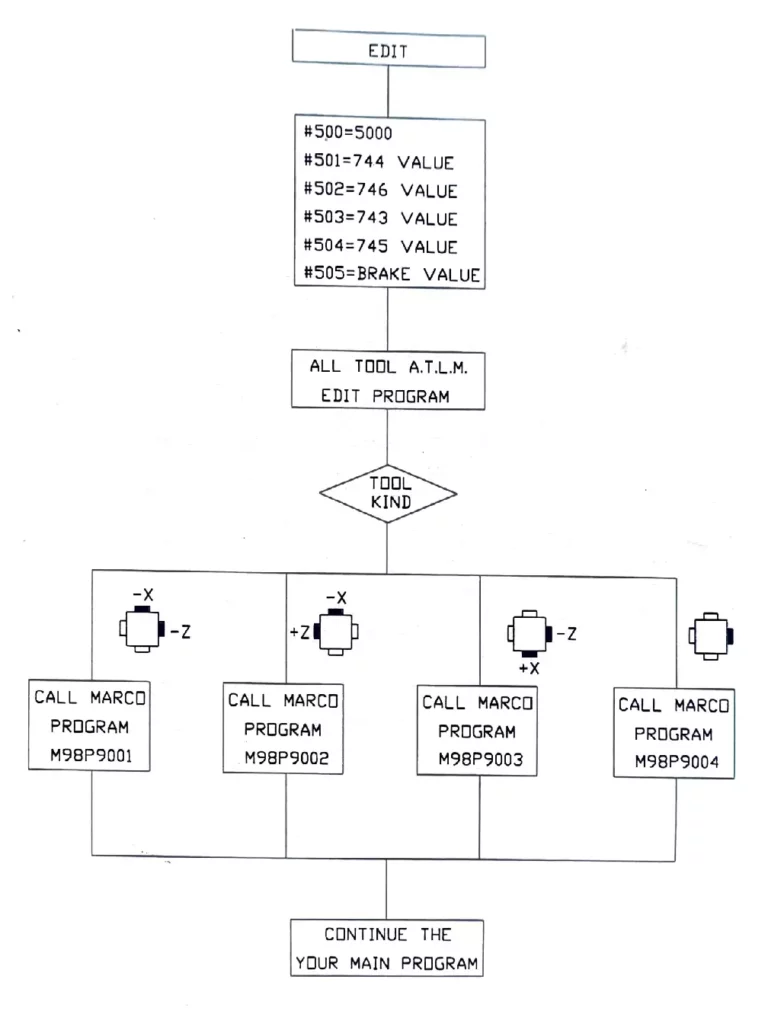
Other tools are in accordance with former step. After a tool works sometimes, desire the tool to make a breakage offset. First change the cutting work piece into more small workpiece (otherwise when tool setter arm down, will hit the cutting workpiece if chuck don’t clamp any workpiece, in screen appear al1007. Then write a program to call subprogram no, 9001 to no. 9004 in depending on what kind of tool
Note: subprogram no. 9001 to no. 9004 can’t be insert in cutting program.


