When programming CNC machines, selecting the correct plane is especially critical during circular interpolation operations. While linear movements can often be executed without changing planes, circular interpolations require a specific plane to define the arc’s orientation. This post will explore the importance of plane selection during circular interpolation and provide guidance on how to implement it effectively.
What is Circular Interpolation?
Circular interpolation involves creating arcs or circles by moving the tool along a curved path. Unlike linear movements, which follow straight lines, circular interpolation requires the CNC machine to calculate and execute smooth, curved paths. To achieve this, the machine must know the plane in which the arc lies.
Why is Plane Selection Important ?
During circular interpolation, the selected plane determines the axes used to define the arc. If the wrong plane is chosen, the arc may not follow the intended path, leading to:
- Incorrect geometry
- Scraped material
- Damaged tools or workpieces
- Increased cycle times
For example:
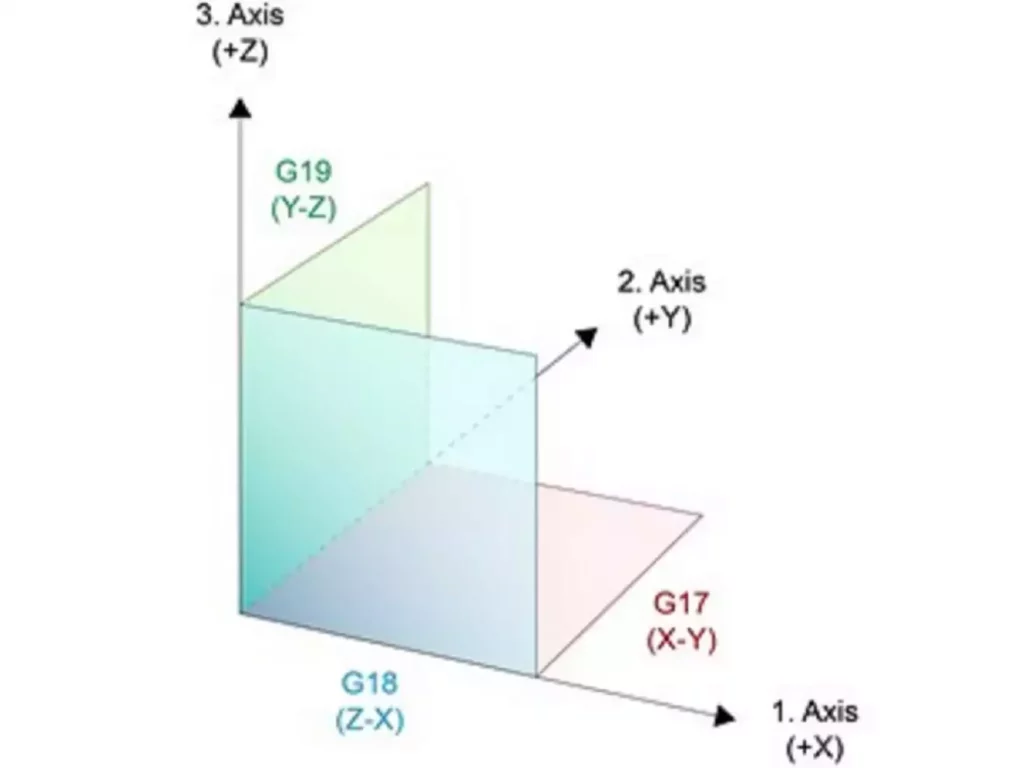
- In the XY plane, arcs are defined using the X and Y axes.
- In the XZ plane, arcs are defined using the X and Z axes.
- In the YZ plane, arcs are defined using the Y and Z axes.
Thus, selecting the appropriate plane ensures that the arc is generated correctly within the desired coordinate system.
How to Select a Plane
Plane selection for circular interpolation is done using G-codes. The following G-codes are standard across most CNC systems:
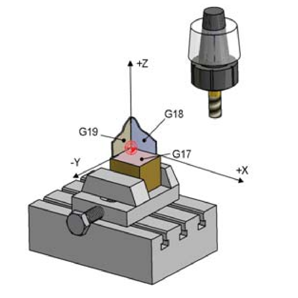
- G17 – XY Plane
- Activates the XY plane for circular interpolation.
- Example:
G17 G02 X50 Y30 I10 J10 F100(Clockwise arc in the XY plane).
- G18 – XZ Plane
- Activates the XZ plane for circular interpolation.
- Example:
G18 G03 X40 Z20 I10 K0 F100(Counterclockwise arc in the XZ plane).
- G19 – YZ Plane
- Activates the YZ plane for circular interpolation.
- Example:
G19 G02 Y60 Z10 J10 K0 F100(Clockwise arc in the YZ plane).

It’s important to note that the plane must be explicitly selected before initiating the circular interpolation command (G02 for clockwise arcs or G03 for counterclockwise arcs).
Best Practices for Plane Selection During Circular Interpolation
- Select the Plane Before Defining the Arc
Always specify the plane before issuing the circular interpolation command. Forgetting to do so can lead to unexpected results, as the machine will default to the last selected plane. - Use Clear Comments
Include comments in your code to indicate when a plane is being changed. For example:
   ; Switch to XY Plane for circular interpolation
G17- Verify with Simulation
Always simulate the program to ensure that the selected plane aligns with the intended arc. Most modern CAM software includes simulation tools for this purpose. - Reset to Default After Use
It’s good practice to reset the plane to the default (usually G17 – XY Plane) at the end of the program to avoid unexpected behavior in subsequent programs.

Example Program Demonstrating Plane Selection
Below is an example of a simple CNC program that demonstrates plane selection during circular interpolation:
%O (CIRCULAR_INTERPOLATION_DEMO)
( Start of Program )
G90       ; Absolute Positioning
G21       ; Metric Units
S1000 M03 ; Set spindle speed to 1000 RPM and start spindle clockwise
( Work in XY Plane for Circular Interpolation )
G17       ; Select XY Plane
G00 X0 Y0 ; Rapid move to origin
G02 X50 Y30 I10 J10 F100 ; Clockwise arc in the XY plane
( Switch to XZ Plane for Circular Interpolation )
G18       ; Select XZ Plane
G00 X0 Z0 ; Rapid move to origin
G03 X40 Z20 I10 K0 F100 ; Counterclockwise arc in the XZ plane
( Switch to YZ Plane for Circular Interpolation )
G19       ; Select YZ Plane
G00 Y0 Z0 ; Rapid move to origin
G02 Y60 Z10 J10 K0 F100 ; Clockwise arc in the YZ plane
( Return to XY Plane )
G17       ; Re-select XY Plane
G00 X0 Y0 ; Return to origin
M05       ; Stop Spindle
M30       ; End of Program
Key Takeaways
- Linear Movements vs. Circular Interpolation: While linear movements can often be performed without explicitly changing planes, circular interpolation requires the correct plane to be selected beforehand. This ensures that the arc is generated accurately within the intended coordinate system.
- Explicit Plane Selection: Always select the appropriate plane (G17, G18, or G19) before initiating a circular interpolation command (
G02orG03). - Simulation and Verification: Use simulation tools to confirm that the selected plane aligns with the intended arc path.
By adhering to these principles, CNC programmers can ensure precise and reliable circular interpolation, minimizing errors and maximizing machining efficiency.


