Understanding CNC Control Panel Symbols
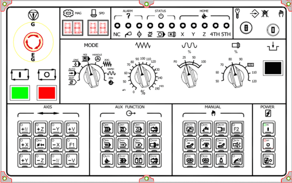
If you’ve ever stood in front of a CNC (Computer Numerical Control) machine, you’ve likely noticed the array of buttons, switches, and symbols on its control panel. These symbols aren’t just decorative they provide critical visual cues that help operators manage machine functions quickly and safely, often transcending language barriers.
These symbols can seem cryptic at first, especially on popular systems, which often use icons instead of text for international compatibility.
Several international standards help standardize symbols, layouts, and ergonomics on machine control panels (including CNC machines) to reduce operator confusion across manufacturers and regions. These promote consistency, safety, and intuitive human-machine interaction, especially through graphical symbols that transcend language barriers.
Key Standards for Graphical Symbols on Control Panels
The most direct standards for ensuring recognizable symbols (e.g., for start/stop, modes, emergency stop, spindle direction) are:
- ISO 7000: Graphical symbols for use on equipment
This provides a comprehensive collection of registered graphical symbols placed on equipment to instruct operators on its operation. It includes symbols for controls like arrows for direction, play/pause for cycle start, and many others common on machine panels. The goal is universal understanding without relying on text. - IEC 60417: Graphical symbols for use on equipment
Maintained by the International Electrotechnical Commission, this database contains symbols specifically for electrical and electronic equipment, including control panels. It overlaps and complements ISO 7000 (often accessed jointly). Symbols here cover functional states, connections, and operations (e.g., power on/off, rotation directions).
These two are often used together as a “one-stop” reference for manufacturers. Many CNC controls (especially Fanuc-style icon-based panels) draw from these to ensure symbols are internationally consistent.
Ergonomics and Layout Standards
To minimize confusion through better design of controls and displays:
- EN 894 / ISO 13850 series: Safety of machinery — Ergonomics requirements for the design of displays and control actuators
This multi-part European/ISO standard (harmonized with EU Machinery Directive) covers: - Part 1: General principles for human interactions.
- Part 3: Specific requirements for control actuators (buttons, switches, joysticks).
- Part 4: Location and arrangement of displays and controls.
It ensures controls are intuitive, accessible, and arranged to prevent errors (e.g., emergency stop prominence, logical grouping of modes).
Safety-Related Control Standards
These indirectly support consistency by requiring reliable and understandable interfaces:
- ISO 13849-1: Safety of machinery Safety-related parts of control systems
Focuses on performance levels for safety functions (e.g., emergency stop, interlocks). While not symbol-specific, it mandates clear indication and actuation to avoid hazards. - IEC 60204-1: Safety of machinery Electrical equipment of machines
Includes requirements for control devices, push-buttons, and symbols (referencing IEC 60417).
How These Reduce Confusion Across Manufacturers/Regions
- Symbols from ISO 7000/IEC 60417 are language-independent, allowing operators to switch between brands (e.g., Fanuc, Siemens, Haas) or countries with less retraining.
- Ergonomic rules in EN 894 ensure similar layouts (e.g., cycle start green, emergency stop red/mushroom).
- Compliance is often required for CE marking (Europe) or global export, pushing manufacturers toward uniformity.
While no single standard mandates exact CNC panel layouts (variations persist for competitive reasons), these norms strongly encourage harmonization. For specific machines, always consult the manufacturer’s manual alongside these standards. If you’re dealing with a particular CNC brand, checking compliance with IEC 60417/ISO 7000 is a good starting point for symbol familiarity.
Common Sections of a CNC Control Panel
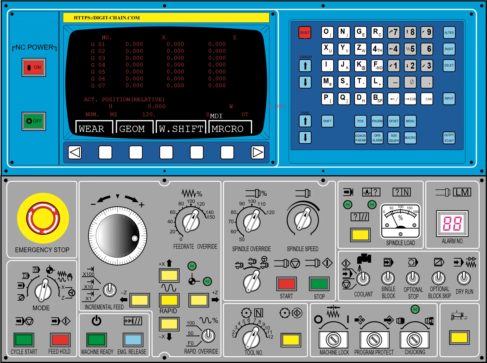
CNC control panels may vary by manufacturer, but they generally follow a logical layout divided into functional areas to streamline operation. Understanding these sections helps operators navigate the machine with confidence:
- Mode Selection Switches: Let you choose between operating modes such as EDIT, AUTO (MEM), MDI (Manual Data Input), JOG, and HANDLE (MPG) each serving a different phase of setup or production.
- Jogging and Manual Controls: Include directional keys or a manual pulse generator (MPG) for precise, manual movement of the X, Y, and Z axes during setup or alignment.
- Program Execution Controls: Feature essential buttons like Cycle Start (▶), Feed Hold (⏸), and Reset, along with override dials to adjust feed rate or spindle speed on the fly.
- Function Keys: Typically labeled soft keys or dedicated buttons for accessing menus like Program, Offsets, Offsets Setting, Position, and Parameters—crucial for programming and machine calibration.
- Spindle and Auxiliary Controls: Manage auxiliary functions such as spindle start/stop, spindle direction (CW/CCW), and coolant on/off, often represented with intuitive pictograms.
- Emergency Stop: Always a large, red, mushroom-shaped button that immediately cuts power to motion systems in an emergency. It’s the most critical safety feature on the panel and requires manual reset.
Familiarity with these zones not only speeds up operation but also reinforces safe and efficient workflow practices especially when switching between tasks like setup, dry runs, and full production.
Why These Symbols Matter
Standardization of these symbols often guided by international norms such as ISO or ANSI ensures that operators can interact with machines across different manufacturers and regions with minimal confusion. For new users, spending time learning these symbols is a worthwhile investment. For teams, clear understanding reduces downtime and prevents accidents.
Pro Tip: Always consult your machine’s specific manual. While many symbols are standardized, slight variations exist between brands like Fanuc, Siemens, Haas, or Mitsubishi. Some modern CNC panels also integrate touchscreens with dynamic icons, but the core functions remain consistent.
Mastering your CNC control panel is the first step toward confident, efficient, and safe machining. Keep this guide handy, and never hesitate to ask for clarification when in doubt precision starts with understanding.
Below is a handy reference table featuring three columns: Button Function, Pictogram (Symbol Description), and Description.
| Button Function | Pictogram | Description |
|---|---|---|
| Emergency Stop | Red circle with a white cross or hand symbol | Immediately halts all machine motion and power in case of danger or emergency. Always prominently placed and requires manual reset. |
| Cycle Start | Right-pointing triangle (▶) | Resumes or initiates the execution of the loaded CNC program. Often green in color. |
| Feed Hold | Two vertical bars (⏸) | Temporarily pauses the program execution while maintaining spindle rotation and coolant flow. Allows safe inspection or intervention. |
| Spindle On/Off | Circular arrow or “S” with on/off indicators | Controls the rotation of the spindle—critical for starting or stopping cutting operations. May have separate forward/reverse buttons. |
| Coolant On/Off | Droplet or water wave symbol | Activates or deactivates the coolant system to manage heat and chip removal during machining. |
| Jog Mode | Four-way arrow (↑↓←→) | Enables manual movement of axes (X, Y, Z) in small increments for setup or positioning. |
| Manual Pulse Generator (MPG) | Rotary dial with tick marks | A handwheel used in conjunction with axis selection to precisely control movement via pulses. |
| Reset | Circular arrow pointing counterclockwise (🔄) | Clears alarms, resets the control system, or cancels the current operation without powering down. |
| Single Block | “SB” or block icon with “1” | Executes one block (line) of the CNC program at a time—useful for testing or debugging. |
| Dry Run | Gear or play symbol with dashed outline | Runs the program without activating the spindle or coolant used to verify tool paths quickly. |