
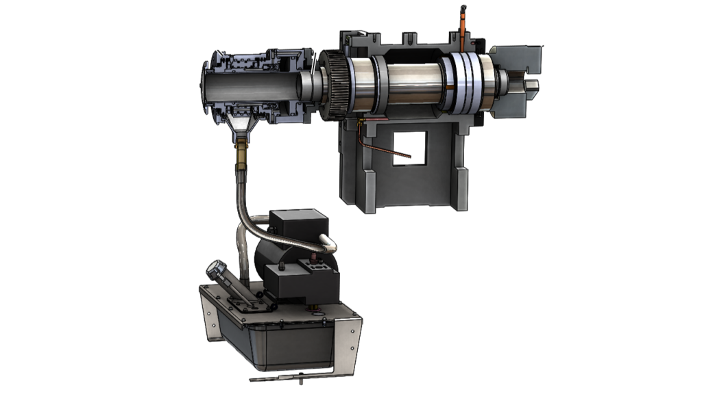
As a machine operator, you interact with the chuck every single cycle. You load the part, hit the cycle start, and trust that the machine is going to hold that workpiece tight while a carbide insert rips metal off it at 3,000 RPM.
But have you ever stopped to think about what’s actually happening behind the spindle when you hear that satisfying clack of the jaws closing?
If you’re used to manual chucks, the transition to a hydraulic system can feel like magic. It’s not magic, though it’s fluid dynamics and mechanical leverage working together. Here is a breakdown of the operating principle and the key components of the hydraulic clamping system on your CNC lathe.
The Operating Principle: From Fluid to Force
At its core, a hydraulic clamping system converts fluid pressure into mechanical force.
When the CNC control sends a command (usually an M10 code to clamp or M11 to unclamp), it triggers a solenoid valve on the hydraulic power unit. This valve directs pressurized oil into the system.
Here is the chain reaction:
- Pressure Builds: Hydraulic oil is pumped into the rear cylinder.
- Piston Moves: The oil pressure pushes a piston inside the cylinder.
- Drawtube Actuates: The piston is connected to a long rod called the drawtube, which runs through the center of the spindle. The piston pulls (or pushes) this drawtube.
- Wedge Mechanism Engages: The drawtube connects to the internal mechanism of the chuck. As the drawtube moves, it forces a set of wedges to slide.
- Jaws Close: These wedges push the master jaws (and your top jaws) inward, gripping the part with thousands of pounds of force.
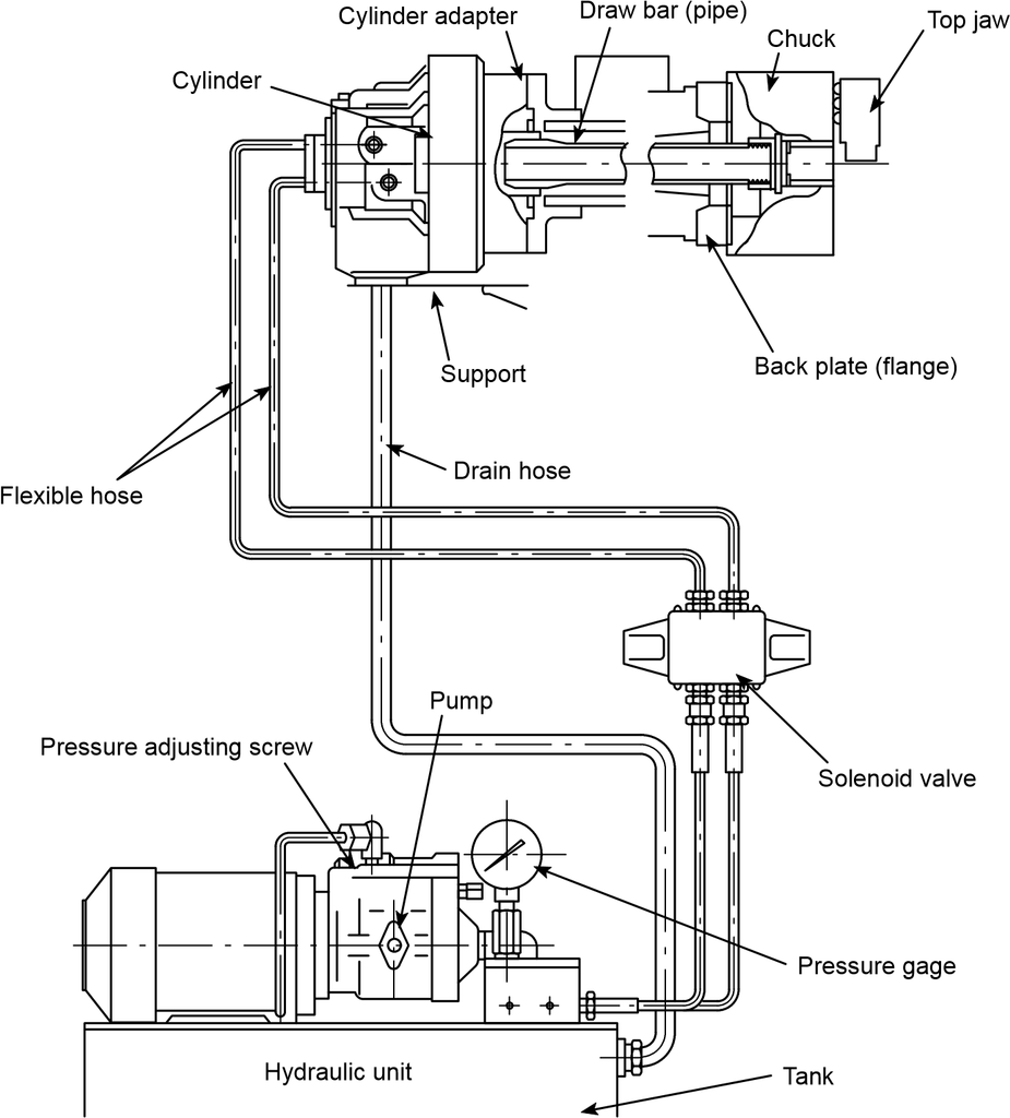
The beauty of this system is consistency. Unlike a manual chuck where clamping force depends on how hard you crank the wrench, a hydraulic system applies the exact same pressure every single time.
The Anatomy of the System: Key Components
To troubleshoot or maintain the system, you need to know the parts. Here are the main players:
1. The Hydraulic Power Unit (HPU)
This is the muscle of the operation. It’s usually a standalone unit (or built into the machine base) containing a pump, a motor, a reservoir for oil, and control valves. It generates the pressure (PSI) required to clamp the part. You can often adjust the pressure here crucial when holding thin-walled parts that might crush under high pressure.
2. The Rotary Union (Swivel Joint)
This is the most critical component for allowing the system to work while the spindle spins. You can’t run a hydraulic hose directly to a spinning cylinder; it would twist and snap.
The rotary union sits at the back of the headstock. It allows hydraulic fluid to pass from a stationary supply line into the rotating cylinder. Operator Tip: If you see oil misting or leaking from the back of the headstock, your rotary union seals are likely worn out.
3. The Hydraulic Cylinder
Mounted directly to the rear of the spindle nose, this cylinder houses the piston. When oil enters the cylinder, it pushes the piston, which physically pulls the drawtube.
4. The Drawtube
This is a long, hollow steel rod that runs the entire length of the spindle bore. It connects the rear cylinder to the front chuck. Because it’s hollow, you can still pass bar stock through it. It translates the linear motion of the rear cylinder into motion at the chuck.
5. The Chuck Body and Wedge Mechanism
This is the part you see at the front. Inside the chuck body, the drawtube connects to a wedge mechanism (often a scroll or wedge design). As the drawtube pulls back, the wedges slide outward, forcing the master jaws inward.
Why This Matters to The Operator
Understanding this system isn’t just for maintenance guys; it makes you a better operator.
- Safety First: Hydraulic systems are tied into the machine’s safety interlocks. A pressure switch ensures the spindle won’t start unless the chuck has reached the correct clamping pressure. Never bypass this switch!
- No More “Cheater Bars”: You don’t need to guess if the part is tight enough. The gauge on the HPU tells you the exact pressure.
- Speed: Many hydraulic chucks allow you to open and close the jaws while the spindle is rotating at a low “crawl” speed, shaving seconds off every cycle.
- Part Protection: By lowering the pressure on the HPU, you can hold delicate aluminum or thin tubing without crushing it something impossible to do consistently with a manual chuck.
A Quick Maintenance Reminder
Hydraulic chucks are robust, but they live in a dirty environment.
- Grease is your friend: The wedge mechanism inside the chuck needs to slide freely. If it gets packed with chips, it will seize. Purge the chuck with fresh grease daily until clean grease comes out.
- Watch the pressure: Keep an eye on the HPU gauge. If the pressure drops during a clamp, you might have a leak in the rotary union or the cylinder seals.
Next time you load a part and hit the cycle start, take a second to appreciate the engineering. It’s a lot more than just a chuck; it’s a high-pressure system designed to keep you safe and your parts precise.


