
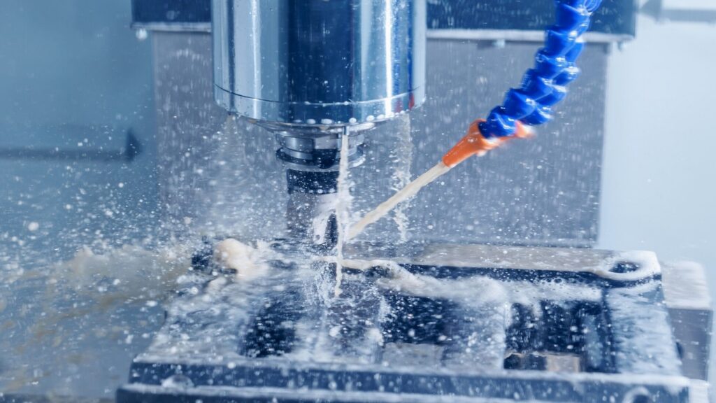
In the high-stakes world of precision manufacturing, the cutting tool gets all the glory. But behind every mirror-like surface finish, tight tolerance, and extended tool life is a complex, circulating ecosystem: the CNC Machine Coolant System.
Whether you run a CNC lathe, a vertical machining center, or a surface grinder, this system is the circulatory network of your machine. It is responsible for removing intense friction heat, forcefully flushing chips, lubricating the cut, and protecting critical machine components from corrosion.
When this system is neglected, the symptoms show up everywhere: poor surface finishes, premature tool wear, thermal drift, clogged nozzles, burnt pump motors, and a shop that smells like a swamp. In this comprehensive guide, we will break down the anatomy of a CNC coolant system, explain its working principles, and provide a crucial maintenance checklist to keep your operation healthy and your parts in spec.
Why the Coolant System Matters
Coolant is not just “wet water”; it is a highly engineered fluid with four critical jobs in the machining process, all facilitated by the system:
- Cooling: It absorbs and carries intense heat away from the cutting edge, the workpiece, and the chips.
- Lubrication: It reduces friction at the tool-workpiece interface, improving surface finish and preventing built-up edge.
- Chip Evacuation: It forcefully flushes swarf out of the cutting zone, preventing recutting and protecting delicate machine ways.
- Protection: It contains corrosion inhibitors that prevent rust on machine tables, castings, and finished parts.
The coolant system is the engineered network that makes these four jobs possible, transforming a static fluid into a dynamic, protective force.
The Anatomy: Main Components of a Coolant System
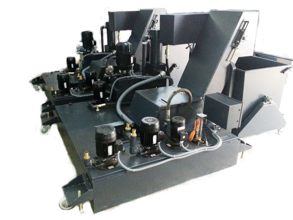
A modern CNC coolant system is not just a simple basin; it is a carefully engineered filtration, pumping, and separation network. In a machine shop environment, where fine metallic particles, tramp oil, and bacterial growth are constant threats, every component plays a vital role.
1. The Reservoir (The Heart)
- Tank Body: Typically constructed from welded steel or stainless steel, located under or beside the machine. Capacities range from ~50 liters on compact machines to several thousand liters on large central systems.
- Dirty (Settling) Chamber: The entry point where returning coolant arrives, carrying chips, fine swarf, and tramp oil. Heavy particles are designed to settle here first.
- Baffles and Weirs: Internal walls that slow the fluid’s velocity and force it to overflow from one chamber to the next. This calm transition is critical for effective sedimentation.
- Clean Chamber: The isolated compartment where the pump draws fluid. Thanks to the baffles, the fluid here should be as free of suspended particles as possible.
2. Pumping & Delivery (The Muscles)
- Standard Coolant Pump: Typically a heavy-duty, submersible centrifugal pump that feeds flood nozzles at low to medium pressure.
- High-Pressure Pump: The muscle for Through-Spindle Coolant (TSC) and deep-hole drilling. These external, multi-stage pumps can reach 20 to 70+ bar, breaking chips and cooling the cutting edge from the inside out.
- Transfer/Return Pump: Moves coolant from the machine base or chip conveyor discharge back into the main system reservoir.
3. Filtration & Separation (The Kidneys)
- Chip Conveyor: The first line of defense. This mechanical or magnetic system continuously removes large swarf from the machine, dropping it into a disposal bin while draining coolant back to the tank.
- Strainers & Mesh Filters: Located at the pump inlet to catch coarse debris before it can damage the pump impeller.
- Paper Band, Cartridge, or Bag Filters: The secondary defense. These remove fine metallic particles, which is absolutely essential for grinding, high-pressure TSC systems, and tight-tolerance aerospace or medical work.
- Magnetic Separator: Highly effective for capturing fine ferrous dust, especially in cast iron or steel grinding applications.
- Tramp Oil Skimmer: As way lube and spindle oil inevitably leak into the sump, they float to the surface. A belt or disk skimmer continuously removes this “tramp oil,” starving anaerobic bacteria of their food source and preserving coolant chemistry.
4. Conditioning & Control (The Nervous System)
- Coolant Chiller / Heat Exchanger: Maintains the coolant at a stable, optimal temperature (often 20°C–22°C / 68°F–72°F). This prevents thermal expansion of the machine structure and workpiece, ensuring repeatable accuracy.
- Automatic Concentration Mixer: Blends water and coolant concentrate to the exact ratio, removing human error from the top-off process.
- Level Switch / Float Sensor: Communicates with the machine’s PLC to warn of low fluid levels, protecting the pump from catastrophic dry-running.
- Aeration Unit (Optional): Circulates and oxygenates the fluid during weekends or extended idle periods to prevent stagnation and bacterial growth.
How It Works: The Coolant System Circuit Step by Step
Tracing the journey of the fluid during a standard machining cycle reveals the elegance of the entire system:
- The Trigger: The CNC program calls for coolant (e.g., M08), and the machine’s PLC activates the coolant pump motor.
- The Suction & Pressurization: The pump draws fluid from the Clean Chamber, passing it through an inlet strainer and building the required pressure.
- The Delivery: Coolant travels through hoses and piping to the flood nozzles, or is routed through the spindle and tool holder for high-pressure TSC machining.
- The Action: The fluid hits the cutting zone, absorbing heat, lubricating the tool, and forcefully ejecting chips from the cut.
- The Return: Gravity pulls the used, chip-laden coolant down through the machine’s way guards and drain pan, back toward the system reservoir.
- The Separation: The fluid and chips hit the Chip Conveyor. Large swarf is lifted out, while the fluid drops into the Dirty Chamber. Heavy fines settle to the bottom, and the fluid slowly overflows the Baffles into the Clean Chamber.
- The Conditioning: As the fluid rests, the Tramp Oil Skimmer cleans the surface, and an optional Chiller stabilizes the temperature. The fluid is now conditioned and ready to be drawn by the pump again.
- The Rest: On M09 or at program end, the PLC halts the pump, and the circuit rests.
The Machine Shop Survival Guide: Coolant System Maintenance Tips
A neglected coolant system is a silent budget killer. It shortens tool life, ruins surface finishes, corrodes expensive machine castings, and creates health hazards for operators. Because coolant chemistry is highly sensitive, proactive, system-wide maintenance is non-negotiable.
Here are the essential maintenance habits to keep your system running at peak performance:
1. Master Your Concentration
- Test Weekly with a Refractometer: Check concentration at least weekly (daily on high-production machines).
- Follow the Data Sheet: A typical range is 5% to 10%, but always defer to your specific coolant manufacturer’s recommendations.
- Avoid the Extremes: Too lean invites rust, poor lubrication, and bacterial growth. Too rich causes foaming, residue buildup, skin irritation, and wasted money.
- Top Off with Pre-Mix: Always add pre-mixed coolant, never plain water, to maintain a stable chemical balance across the entire system.
2. Monitor pH and Fluid Health
- Know the Sweet Spot: Healthy water-based coolant is mildly alkaline, typically targeting a pH of 8.5 to 9.5.
- Watch for Warning Signs: A dropping pH is the earliest indicator of bacterial activity. Be on high alert for a rancid “rotten egg” smell, slimy deposits, dark discoloration, or separated oil.
3. Wage War on Tramp Oil
- Leaking hydraulic and way lube block oxygen exchange at the fluid’s surface, creating a haven for anaerobic bacteria.
- Ensure your skimmer runs daily, use oil-absorbing pads, and proactively track down and fix machine leaks at the source.
4. Purge System Sludge
- Even with great filtration, fine “swarf sludge” will accumulate at the bottom of the dirty chamber over time, degrading fluid life.
- Schedule a complete system drain, scrub, and refill. Depending on your shop environment and materials cut, this may range from quarterly to annually. Clean the chip conveyor, strainers, and tank walls during this downtime.
5. Maintain Filters and Delivery Nozzles
- Replace paper band, bag, or cartridge filters at the recommended interval, or immediately when the pressure gauge indicates a clog. A restricted filter overworks the pump and starves the cutting zone.
- Regularly verify that flood nozzles are aimed correctly and are free of chip blockages. A misaligned nozzle is a wasted opportunity for tool cooling.
6. Control System Temperature
- Hot coolant loses its cooling capacity, evaporates faster, and accelerates bacterial growth.
- If equipped with a Chiller, clean the air intake fins and check refrigerant levels regularly. Stable coolant temperature is the secret to preventing thermal drift in precision machining.
7. Protect the Pump and Plumbing
- Never let it run dry. Dry-running destroys mechanical seals in minutes.
- Listen for the “marbles in a blender” sound of cavitation, which indicates a clogged inlet strainer or an air leak on the suction side. Check pump seals regularly for weeping.
8. Protect Your People
- Mandate the use of gloves and barrier creams to prevent prolonged skin contact with coolant.
- Ensure mist collectors are functioning properly where oil mist is generated.
- Dispose of spent coolant strictly according to local environmental regulations. Never pour it down a standard drain.
Common Problems and Quick Checks
| Symptom | Likely Cause | First Check |
|---|---|---|
| No coolant flow | Pump failure, clogged strainer, low fluid level | Tank level, inlet strainer, pump motor rotation |
| Weak pressure | Worn impeller, clogged filter, air leak in suction line | Filter pressure gauge, suction fittings, pump seals |
| Excessive foaming | Over-concentration, air intake, wrong coolant type | Refractometer reading, check return line splash |
| Foul “swamp” smell | Bacterial/fungal growth, heavy tramp oil | pH level, oil on surface, sludge at tank bottom |
| Rust on parts/ways | Low concentration, severe pH drop | Concentration and pH test strips |
| Poor surface finish | Dirty coolant, incorrect flow, chip recutting | Filter condition, nozzle alignment, coolant pressure |
Conclusion
The CNC machine coolant system is easy to overlook, but it directly dictates tool life, surface quality, machine accuracy, and operator health. By understanding its anatomy from the settling chambers and high-pressure pumps to the critical skimmers and chillers you can diagnose issues before they result in scrapped batches or catastrophic spindle failures.
Implementing a strict, simple routine of checking concentration, pH, tramp oil, filters, and temperature will exponentially extend your fluid life. In precision machining, a clean and well-managed coolant system is always cheaper than the scrap and downtime it prevents.


