In the heart of every machining center, surrounded by the whirring of servos and the scent of cutting fluid, lies the true nexus of control: the operator’s panel. While CNC machines are marvels of automation, their power is channeled directly through this interface. It’s the console where human intuition meets digital precision.
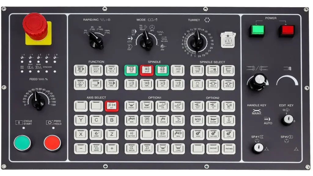
To the untrained eye, a panel can look like a complex jumble of buttons and knobs. But for a skilled CNC operator, it’s a logically organized instrument. By grouping its functions into dedicated sections, manufacturers create an intuitive workflow. Let’s take a tour of a typical panel, using a specific example to break down exactly what each cluster of controls does.
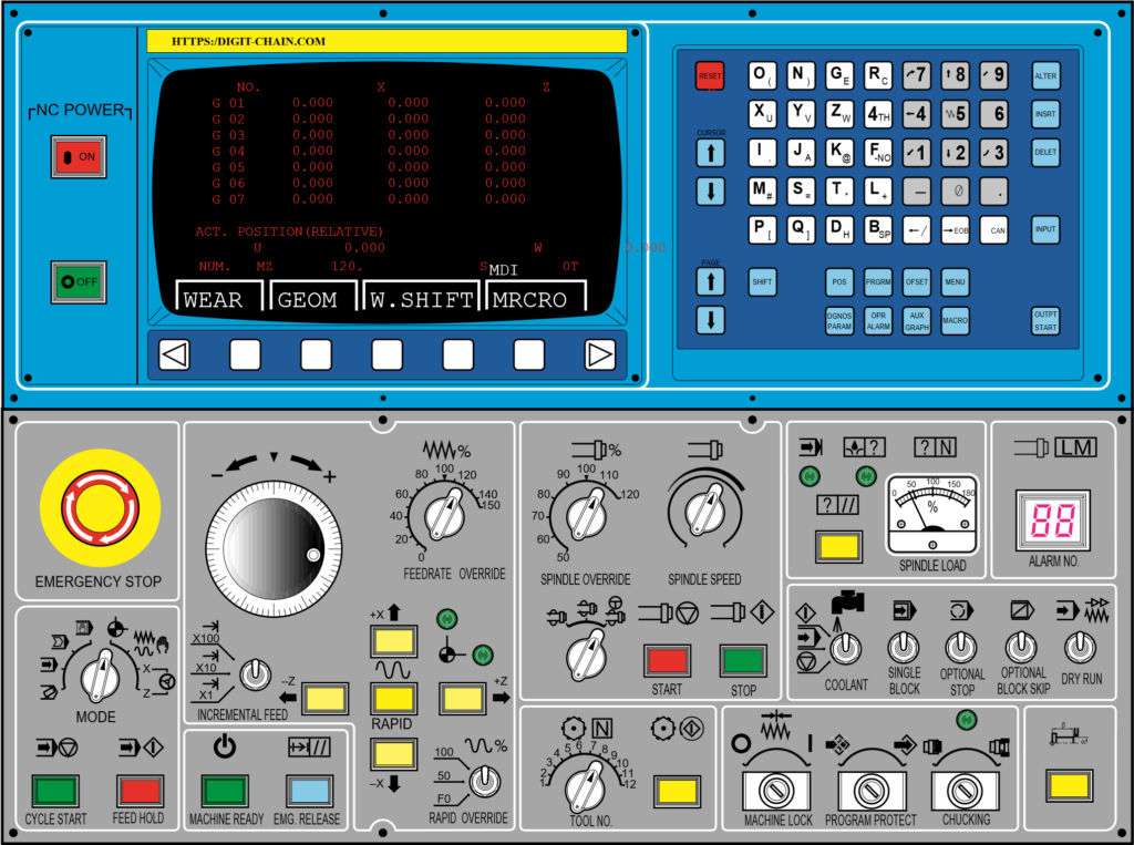
1. The MODE Selector: Defining the Machine’s State
This is the foundational control cluster. The MODE selector switch dictates the machine’s overarching behavior and is the first step in any operation. It’s a critical safety feature, ensuring the machine only responds to commands appropriate for the task at hand.
- EDIT: This mode allows the operator to view, create, or modify the part program stored in the machine’s memory.
- MEM (Memory) or AUTO: This is the standard production mode where the machine executes a full program from its internal memory.
- MDI (Manual Data Input): This mode acts as a command line, allowing the operator to input and execute single lines of code (e.g., “M03 S1000;” to start the spindle) without running a full program.
- DNC (Direct Numerical Control): Used for running very long programs that are streamed directly from an external computer.
- HANDLE or MPG (Manual Pulse Generator): This mode engages the electronic handwheel, allowing for precise, incremental manual control of the machine axes.
- JOG: In this mode, pressing and holding the axis direction buttons moves the machine at a set, controlled feed rate.
- RAPID: This is a variation of JOG mode where the axis buttons move the machine at its maximum traverse speed, used for quickly covering long distances.
- ZRN (Zero Return/Home): This is a safety and setup mode used to automatically send the machine axes to their mechanical reference points to set up the machine coordinate system.
These modes define the machine’s behavior and are selected via a rotary switch on the operator’s panel.
2. The Override Dials: The Operator’s Real-Time Tuning Knobs
A CNC program is a set of static instructions, but machining is a dynamic process. The override dials are the operator’s primary tool for adapting the program to real-world conditions.
- Feedrate Override (%): This rotary dial, often marked with a scale from 0% to 120% or more, allows the operator to dynamically scale the programmed feed rate. If a cut sounds aggressive or looks rough, the operator can dial it down to 70%. If a light finishing pass has room for more efficiency, they might cautiously increase it to 110%.
- Spindle Speed Override (%): This performs the same function for the spindle’s RPM. This is vital for adapting to different tooling or material hardness on the fly.
These knobs exemplify the operator’s irreplaceable role. They use their senses and experience, fine-tuning the machine’s performance in real-time for optimal quality and tool life.
3. The AXIS Control Cluster: Taking Manual Control
This group of buttons is the operator’s direct line to physically moving the machine. Its function is directly tied to the MODE selector.
- Axis Direction Buttons (+X, -X, +Y, -Y, +Z, -Z): These buttons, often arranged in a intuitive plus-sign pattern, move the machine along its linear axes. In JOG mode, they move the machine continuously. Their relationship with the MODE is key; they are inactive in AUTO and superseded by the handwheel in HANDLE mode.
- AUX FUNCTION (e.g., +IV, +V): These buttons typically control additional axes, such as a rotary table (A, B, or C axes) or other auxiliary functions specific to the machine’s configuration.
4. The Cycle and Manual Control Section: Executing the Work
This is the “command deck” for program execution and manual machine functions.
- Cycle Start (often a green button): The “Go” command. It begins program execution in AUTO mode or a single command in MDI.
- Feed Hold (often a red button): The “Pause” button. It immediately halts all axis movement while typically keeping the spindle running. This is used to inspect a cut, clear chips, or check a dimension without resetting the entire process.
- MANUAL Controls: This set of buttons gives the operator direct command over key machine functions, independent of any program:
- POWER ON/OFF: Controls main power to the control system.
- Spindle Start/Stop: Manually controls the spindle rotation.
- Coolant On/Off: Manually activates the coolant pump.
- Tool Change: Initiates a manual tool change sequence.
The Operator’s Workflow: A Panel in Action
Let’s see how these grouped functions work together in a typical scenario:
- Setup: The operator rotates the MODE to HANDLE. The axis direction buttons are now inactive. Using the handwheel, they meticulously touch off a tool to set the Z-axis offset.
- Positioning: They switch the MODE to JOG. Now, they use the AXIS direction buttons to quickly move the spindle to the approximate corner of the workpiece to set the X and Y work offsets.
- Verification: They switch to AUTO mode and use the control’s graphics display to simulate the toolpath.
- First Run: With their hand resting near the Feed Hold button and the Feedrate Override dial, they press Cycle Start. They carefully observe the first cut, dialing the feed down to 60% to ensure a smooth entry.
- Production: For the next part, they run the cycle at 100% override but use Feed Hold periodically to pause and blow chips away from a critical feature.
- Intervention: A chip is caught in the tool. They hit Feed Hold, then use the MANUAL Coolant and Spindle buttons to clear it before resuming.
Conclusion: Mastery Through Understanding
The CNC operator panel is not a random assortment of controls but a carefully organized control center. By understanding the logic behind its groupings MODE, Override, AXIS, and MANUAL controls—an operator can move from simple button-pushing to true command. It transforms from a confusing array of inputs into a powerful instrument, allowing the skilled professional to conduct the symphony of metal cutting with precision, safety, and efficiency. Mastery of this panel is what separates a button-pusher from a master craftsperson.


