In the high-stakes world of industrial automation, micron-level precision dictates product quality. It also determines production speed and operational efficiency. One often-overlooked component plays a pivotal role: the encoder. More specifically, the alignment of that encoder. While motors, drives, and controllers steal the spotlight, encoder alignment is a quiet, meticulous process. It ensures the encoder’s rotational axis is perfectly coaxial with the shaft it’s measuring. This process is the unsung hero of accurate motion control. Get it wrong, and even the most advanced servo system will struggle. Get it right, and your entire production line hums with flawless reliability.
This post dives deep into encoder alignment. It covers what encoder alignment is and why it matters. You’ll learn how to do it correctly and understand the consequences of neglect. The post also discusses the evolving technologies making alignment easier than ever. Whether you’re a maintenance technician, an automation engineer, or a plant manager responsible for up-time, understanding encoder alignment is non-negotiable.
What Is Encoder Alignment?
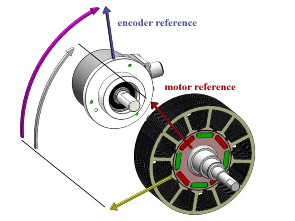
At its core, encoder alignment involves precisely positioning an encoder mechanically. It also requires angular alignment relative to the rotating shaft it is monitoring. Encoders whether optical, magnetic, or resolver-based convert mechanical motion (rotation or linear displacement) into electrical signals that feedback to a controller. This feedback is essential for closed-loop control systems that regulate speed, position, and torque.
But here’s the catch: encoders are not magic boxes. They measure motion as they perceive it. If the encoder’s sensing element is misaligned whether axially (along the shaft), radially (off-center), or angularly (tilted) it will report erroneous data. This misalignment introduces commutation errors, position drift, and velocity ripple, all of which degrade system performance.
There are three primary types of misalignment to watch for:
- Axial Misalignment: The encoder face is not perpendicular to the shaft’s axis. This causes the sensing element to “see” the shaft moving in and out, creating false position signals.
- Radial Misalignment: The encoder’s center is offset from the shaft’s centerline. This induces a wobble, leading to cyclic position errors as the shaft rotates.
- Angular Misalignment: The encoder is tilted relative to the shaft’s rotational plane. This is particularly insidious in high-resolution systems, as even a fraction of a degree can cause significant signal distortion.
All three types can occur simultaneously, and the cumulative effect is often far worse than any single error.
Why Encoder Alignment Matters: Beyond “It Should Be Straight”
You might think, “It’s just a little off how bad can it be?” The answer: extremely bad especially in modern high-precision applications.
Consider a CNC machining center cutting aerospace components. The encoder on the spindle motor must provide sub-micron positional accuracy. A 0.1° angular misalignment might seem negligible. However, in a 100 mm diameter encoder wheel, that equates to a radial displacement of over 87 microns. This displacement is more than three times the width of a human hair. That’s enough to ruin a precision gear tooth or cause surface finish rejection.
In packaging lines, misalignment causes inconsistent labeling or sealing, leading to product waste and customer returns. In robotic arms used for surgical or electronics assembly, encoder misalignment can result in dangerous positional errors.
The financial implications are staggering. A 2024 study by the International Society of Automation (ISA) reveals that encoder misalignment causes significant issues. It accounts for 17% of unscheduled downtime in automated manufacturing plants. The cost? An average of $12,000 per hour in lost production, not including scrap, rework, or safety incidents.
Moreover, misalignment doesn’t just cause immediate errors it accelerates wear. A misaligned encoder exerts uneven torque loads on couplings, bearings, and shafts. Over time, this leads to premature mechanical failure, increasing maintenance costs and reducing equipment lifespan.
The Consequences of Poor Alignment: A Cascade of Failure
Poor encoder alignment rarely manifests as a single catastrophic failure. Instead, it triggers a cascade of subtle, compounding problems:
- Position Drift: The system believes it’s at position X, but is actually at X+δ. This causes parts to be machined too long, extruded too thin, or assembled off-center.
- Velocity Ripple: The controller receives fluctuating feedback signals, causing jerky motion. This is especially damaging in applications requiring smooth, continuous motion—like film extrusion or textile weaving.
- Increased Motor Current: The drive pushes more current to compensate for perceived position errors. This leads to overheating and reduces motor life.
- Control Instability: High-resolution servo loops become unstable, oscillating or hunting around the setpoint. This can trigger alarms or force the system into safe shutdown.
- False Diagnostics: Maintenance teams waste hours chasing phantom electrical faults, when the real culprit is a slightly crooked encoder.
One real-world example: A pharmaceutical bottling line in Germany experienced intermittent capping failures. After weeks of troubleshooting motor drives and sensors, technicians discovered a 0.05mm radial misalignment in the encoder coupling caused by a slightly warped mounting plate. Realigning the encoder reduced rejects by 98%.
How to Align an Encoder: A Step-by-Step Guide
Proper encoder alignment isn’t guesswork. It’s a disciplined process requiring the right tools and patience. Here’s a practical, industry-proven procedure:
Step 1: Power Down and Isolate
Always lock out and tag out (LOTO) the system. Never attempt alignment on a live machine.
Step 2: Remove the Encoder
Carefully disconnect the encoder from the shaft. Inspect the shaft end for burrs, wear, or damage. Clean both the shaft and encoder bore with isopropyl alcohol and lint-free cloths.
Step 3: Check Shaft Runout
Use a dial indicator mounted on a stable stand to measure radial and axial runout of the shaft itself. If the shaft is bent or worn beyond manufacturer specs (typically < 0.01mm TIR), repair or replace it before installing the encoder.
Step 4: Use Precision Coupling
Never use a simple flexible coupling unless it’s specifically rated for encoder applications. Use a beam coupling or bellows coupling both designed for zero backlash and minimal misalignment tolerance. Avoid Oldham couplings for high-resolution encoders; they introduce angular error.
Step 5: Mount the Encoder
Slide the encoder onto the shaft using a non-marring tool (brass or plastic drift). Do not hammer it. Tighten set screws evenly and gradually in a criss-cross pattern. If using a clamping hub, torque to manufacturer specs using a calibrated torque wrench.
Step 6: Verify Alignment with a Laser Alignment Tool
This is where modern technology shines. Use a laser shaft alignment system (e.g., Fluke 830, Misumi LaserAlign, or Renishaw RMP60). These devices project a laser beam along the shaft axis and measure deviations at the encoder flange with micron-level accuracy.
- Set the laser base on the motor shaft.
- Place the receiver on the encoder flange.
- Rotate the shaft 360° and record the readings.
- Adjust the encoder’s position (using shims or adjustable mounts) until both radial and axial deviations are below 0.005 mm.
Pro Tip: Perform this check at room temperature. Thermal expansion can cause alignment drift if the machine is hot.
Step 7: Reconnect and Validate
Reconnect the encoder cables and power up. Use your motion controller’s built-in diagnostic tools to monitor the encoder’s raw counts or position error over a full rotation. Look for sinusoidal noise patterns these indicate angular misalignment. If present, recheck your mechanical setup.
Step 8: Document and Schedule Recalibration
Record the alignment readings, date, and technician. Schedule periodic checks especially after any mechanical disturbance (belt changes, motor replacements, or seismic events).
Emerging Technologies: Making Alignment Simpler
The good news? Encoder alignment is becoming less of a black art and more of a streamlined process.
- Integrated Alignment Sensors: New encoders from manufacturers like CUI Devices and Heidenhain now include built-in tilt and offset sensors. These sensors communicate alignment errors directly to the PLC via IO-Link.
- Smart Couplings: Companies like Ruland and Lovejoy offer couplings with integrated alignment indicators. These couplings have color-coded rings. The rings turn green when within tolerance.
- Augmented Reality (AR) Guides: Leading OEMs are embedding AR instructions into maintenance apps. Technicians point their tablet at the encoder, and an overlay shows exactly where to adjust shims.
- AI-Powered Predictive Alignment: Some IIoT platforms now analyze encoder signal harmonics in real time. If a 1x or 2x RPM frequency spike appears in the signal spectrum, the system identifies potential misalignment. This happens before it causes failure.
These innovations are reducing alignment time from hours to minutes and preventing countless hours of downstream downtime.
Common Misconceptions Debunked
Let’s clear up some myths:
- Myth: “The encoder doesn’t need to be perfectly aligned it’s just a feedback device.”
Reality: Feedback is only as good as the input. An encoder is the “eyes” of the control system. Garbage in = garbage out. - Myth: “If the machine runs fine, the alignment must be okay.”
Reality: Many systems run “fine” until they suddenly fail catastrophically. Misalignment is a silent killer. - Myth: “I replaced the encoder why is it still acting up?”
Reality: If you didn’t realign the new encoder, you just installed a new sensor on an old problem. - Myth: “Only high-end machines need precision alignment.”
Reality: Even low-cost packaging lines benefit. A 0.1% improvement in alignment can reduce product waste by 5–10%, paying for the alignment tool in days.
Best Practices for Long-Term Success
- Train Your Team: Make encoder alignment part of standard maintenance training. Include visual aids and hands-on practice.
- Standardize Tools: Keep calibrated torque wrenches, dial indicators, and laser alignment kits on every shift.
- Use Quality Components: Cheap couplings and mounting plates are false economy.
- Log Everything: Maintain a digital log of all encoder installations and alignments.
- Don’t Ignore Vibration: Increased vibration is often the first symptom of encoder misalignment. Investigate immediately.
Final Thoughts: Alignment Is Not Optional It’s Foundational
In the age of Industry 4.0, data, predictive analytics, and autonomous systems dominate. We sometimes forget that the foundation of all automation is mechanical precision. No algorithm can compensate for a misaligned sensor. No AI can fix a bent shaft.
Encoder alignment is not a task to be rushed. It’s a ritual of care a commitment to quality, reliability, and operational excellence. It’s the difference between a machine that runs and a machine that thrives.
As you walk through your facility this week, take a moment to look at your encoder mounts. Are they clean, tight and aligned? If you’re unsure, don’t guess measure.
Because in automation, the smallest misalignment can lead to the largest losses. The best engineers aren’t the ones who fix the biggest problems. They are the ones who prevent them before they happen.
Align your encoders. Protect your production.
© 2025 digit-chain. All rights reserved. Reprint with permission.


