PART 1: FANUC 31i-B
The Kinematic Reality
Fanuc dominates North American/Asian 5-axis shops (DMG MORI, Makino, Okuma). Its strength modular G-codes becomes a weakness when kinematics are ignored. On a head-table machine (e.g., Makino D500), the A/B axes pivot the spindle. A G-code error here doesn’t just misposition the tool it makes the entire head assembly collide with fixtures. Your post-processor must map vectors to this physical chain.
Error 1: Rotary Overtravel (Alarm 010)
Symptom: Machine halts at N145 G1 X12.3 Y-5.1 B118.0 with “ALARM 010: B+ LIMIT”.
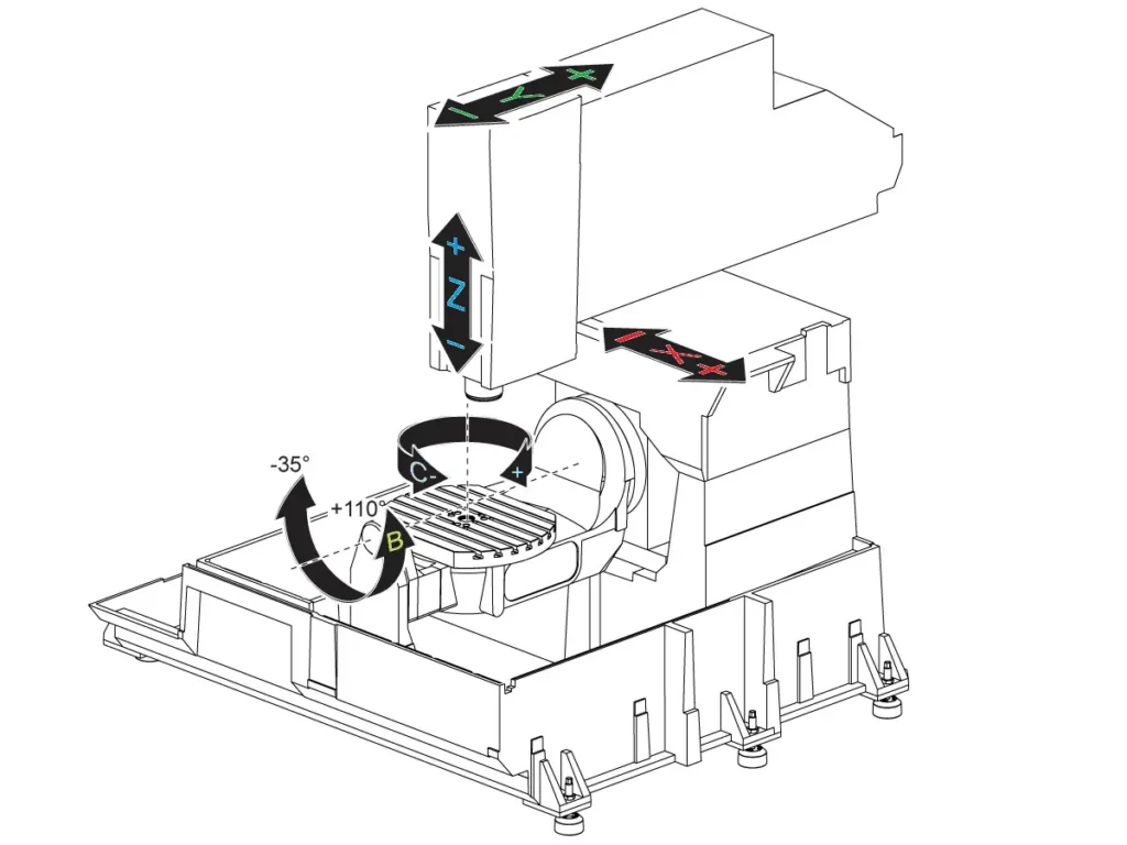
Kinematic Root Cause: Your Okuma MU-4000V’s B-axis physically stops at +115°. The CAM software calculated B118° for optimal cutting but the post didn’t clamp it.
Fanuc-Specific Fix:
- Parameter #14001 = 1 (Rotary Limit Avoidance) forces the controller to auto-clamp axes.
- Post-processor configuration: Define exact limits. Bad output:
G43.4 H1 Z50.G1 X10.0 Y0 B118. F1000
Corrected output:G43.4 H1 Z50.G1 X10.0 Y0 B115. F800(Clamped to max B)G65 P9810 X10.2 Y-0.3(Custom macro reorients vector within limits)
Error 2: TCP Path Deviation
Symptom: Perfect 3-axis roughing, but 5-axis finishing shows 0.4mm scallops on a turbine blade.
Kinematic Root Cause: On head-head machines (e.g., Hermle C42), TCP (G43.4) requires offsets accounting for the distance from spindle face to pivot point. Using standard 3-axis H-values ignores this offset.
Fanuc-Specific Fix:
- Dedicated TCP offsets:
H51for Tool 1 (measured at machine zero via dial indicator at 4 orientations). - Critical parameter:
#5003 = 2(TCP Measurement Mode).
Bad code:G43 H1 Z100.G43.4 H1 Z50.(Uses 3-axis offset!)
Correct code:G43.4 H51 Z50.(H51 = TCP-calibrated offset)
Error 3: Singularity Flips
Symptom: B-axis violently snaps from +45° to -135° mid-cut on a medical implant.
Kinematic Root Cause: At vertical tool orientations (I0 J0 K±1), the B-axis solution becomes non-unique on head-table machines. Fanuc picks the mathematically shortest path a 180° flip.
Fanuc-Specific Fix:
- Enable AI Advanced Preview Control:
G08 P1 Q1 - Parameter #14020 = 1 (Singularity Avoidance)
- Force smooth transitions:
G08 P1 Q1G1 X10 Y0 Z30 I0 J0.707 K0.707 F1000G53.1 P1(Enables orientation smoothing)G1 X12 Y-2 Z28 I0.1 J0.693 K0.707 F1000(Gradual vector change)
Your Fanuc 5-Axis Survival Kit
- Polar Interpolation (G12.1):
G17 G12.1(XY plane) →G1 X50. Z-10. C45.(C=angle). Always cancel withG13.1. - 3D Circular Interpolation (G02.4):
G17.1→G02.4 X50 Y0 Z-5 I10 J0 K-5 P360 F200(Helix). - Look-Ahead (G08 P1): Mandatory for NURBS. Omission causes feedrate drops and chatter.
Actionable Checklist
- Verify rotary limits in post-processor profile (machine-specific, not CAM defaults).
- Calibrate TCP offsets (H51+) using a master sphere never reuse 3-axis offsets.
- Enable
G08 P1and Parameter #14020 for all 5-axis contouring. - Dry run at 5% feedrate while monitoring axis load meters.
PART 2: SIEMENS 840D sl
The Kinematic Reality
Siemens 840D sl (DMG MORI, Hermle, Chiron) uses frames and transformations instead of raw axes. A tool vector isn’t IJK it’s a direction in a work coordinate system transformed by kinematics. On a table-table machine (e.g., DMU 80 P), a B-axis limit isn’t just an angle it’s a collision boundary between part and fixture. Ignore this, and TRAORI becomes your enemy.
Error 1: Rotary Limit Exceeded (Alarm 25030)
Symptom: Cycle stop at N210 G1 X-15.0 Y8.2 B118.0 with “25030 Axis B Exceeds Physical Limit”.
Kinematic Root Cause: Your DMG MORI DMU 60’s B-axis maxes at +115°. The CAM toolpath crossed this during a pocket cleanup, but the post didn’t use Siemens’ AXIAL function.
Siemens-Specific Fix:
- AXIAL function in post-processor:
AXIAL(B, LIMITS: -30, 115) - Controller auto-reorients:
TRAORIG1 X-15.0 Y8.2 B115. F800(Clamped to 115°)SUPA G0 X-14.8 Y8.5(Short intermediate move to avoid singularity)G1 X-12.0 Y10.0 B110. F1000
Error 2: TCP Calibration Drift
Symptom: First part perfect, second part gouged after tool change.
Kinematic Root Cause: Siemens separates tool data from TCP data. If the tool table entry lacks TOOL_TCP=1, TRAORI uses generic offsets. On head-head machines (e.g., Starrag Ecospeed), this ignores pivot-point geometry.
Siemens-Specific Fix:
- Tool table setup:
TOOL T1D1TOOL_TCP = 1(Critical flag!)LENGTH = 150.0(Total offset including pivot) - Explicit
TRAORIframe:TRAORI (X0 Y0 Z0 A0 B0)(Kinematic zero definition)G1 X10 Y0 Z30 B45 F1000
Error 3: Uncontrolled Singularity Crossing
Symptom: Sudden B-axis jump during impeller machining, causing chatter marks.
Kinematic Root Cause: At tool vectors near [I0 J0 K-1], the solution flips on table-table machines. Default motion planning prioritizes speed over stability.
Siemens-Specific Fix:
- REACH (Runtime-Extended Axis Control for High dynamics):
REACH(FLIP_AVOIDANCE, YES)REACH(SINGULARITY_SPEED, 0.1)(Reduces feedrate to 10% near singularity) - Intermediate blocks:
G1 X10 Y0 Z30 B45 C0 F1000SUPA G0 B44.9 C0.1(Micro-adjust to stay on safe side)
Your Siemens 5-Axis Survival Kit
- Polar Interpolation (G112):
G112→G1 RP=50 AP=45 Z-10 F200(RP=radius, AP=angle). Cancel withG113. - Feedrate Forward (FFWON):
FFWONbefore complex moves. Prevents feedrate drops at block junctions. - Collision Avoidance: Activate in ShopMill via
CYCLE 78. Uses full tool/holder model.
Actionable Checklist
- Configure
AXIALlimits in post-processor matching machine specs. - Flag every 5-axis tool with
TOOL_TCP=1in tool management. - Always enable
REACH(FLIP_AVOIDANCE)for aerospace/medical contours. - Run simulation with
GRAPHICS SIMULATION > MACHINE MODELand collision detection ON.
PART 3: HEIDENHAIN TNC640
The Kinematic Reality
Heidenhain (Hermle, GF Machining, Starrag) uses conversational cycles for 5-axis control. Its power lies in kinematic transparency but errors arise when cycles aren’t chained correctly. On a table-table machine (e.g., Hermle C32 U), the B/C axes rotate under the part. A vector error doesn’t cause drift it rams the fixture because the controller trusts your cycles.
Error 1: Hard Limit Collision
Symptom: Machine slams E-stop at L X+20 Y-10 Z+5 B+118 with “Axis B Limit Violated”.
Kinematic Root Cause: Your Hermle’s B-axis is mechanically limited to +115°. The post omitted Heidenhain’s CYCL 7 (Rotary Axis Limitation), so the controller attempted an impossible move.
Heidenhain-Specific Fix:
- CYCL DEF 7 before motion:
CYCL DEF 7.0 ROTARY AXIS LIMITCYCL DEF 7.1 B-30 +115(Exact machine limits)CYCL DEF 7.2 C0 +360L X+20 Y-10 Z+5 B+115 FMAX(Controller auto-clamps B)
Error 2: Uncalibrated TCP
Symptom: First operation perfect, second operation crashes tool into fixture after tool change.
Kinematic Root Cause: Heidenhain requires per-tool TCP calibration. TCPM ON without calibration uses default offsets, ignoring pivot-point geometry on head-table machines.
Heidenhain-Specific Fix:
- Per-tool calibration cycle:
CYCL DEF 32.0 TCP CALIBRATIONCYCL DEF 32.1 TOOL 1CYCL DEF 32.2 MEASURING POINT 1L X+100 Y0 Z-50 R0 FMAX(Touch sphere at orientation 1)L B+30 FMAX(Repeat at 4+ orientations)
Controller auto-calculates pivot offsets. Never skip this.
Error 3: Vector Flip at Vertical
Symptom: During mold finishing, B-axis flips 180° when tool points straight down.
Kinematic Root Cause: At [I0 J0 K-1], infinite B/C solutions exist on table-table machines. Default motion planning selects the shortest angular path a violent flip.
Heidenhain-Specific Fix:
- Dynamic Path Transformation (M128) + Singularity Handling:
M128L X+10 Y+0 Z+30 B+45 C+0 FMAX M126(M126 = TCP with singularity avoidance)L X+12 Y-2 Z+28 B+44.8 C+0.1 FMAX(Controller nudges path away from singularity) - Explicit vector damping: Use
K-0.999instead ofK-1.0in critical zones.
Your Heidenhain 5-Axis Survival Kit
- 3D Circular Interpolation:
CC X+50 Y+0 Z-5(Circle center) →CD X+60 Y+0 Z-10 DR-(Direction). - Look-Ahead Filter (LFA):
LFA 1000(Buffers 1,000 blocks). Critical forM128smoothness. - Vector Logging:
PRINT "I=" IPOS " J=" JPOS " K=" KPOSduring dry runs to validate vectors.
Actionable Checklist
- Insert
CYCL DEF 7at program start for every 5-axis job. - Run
CYCL DEF 32(TCP calibration) after every tool change or head maintenance. - Use
M128+M126for all finishing contours near vertical orientations. - Simulate in
TEST RUNmode with3D VIEWshowing tool + fixture models.
The Unifying Principle
Whether Fanuc, Siemens, or Heidenhain 5-axis G-code doesn’t command axes. It commands physics. A B118° command isn’t a number; it’s a 200kg rotary table hitting a steel stop bolt. An uncalibrated TCP offset isn’t a parameter; it’s your $1,200 cutter burying itself in a titanium workpiece. These controls provide tools (G43.4, TRAORI, M128) to master kinematics, but only if you respect their machine-specific logic.
Stop treating your post-processor as a black box. Demand kinematic models from your CAM vendor. Calibrate offsets weekly. Simulate every program with collision detection. The difference between a crashed spindle and a flawless aerospace impeller is measured in lines of G-code and the milliseconds between E-stop presses. Master your control’s dialect, command the kinematics, and make chips not scrap.


