
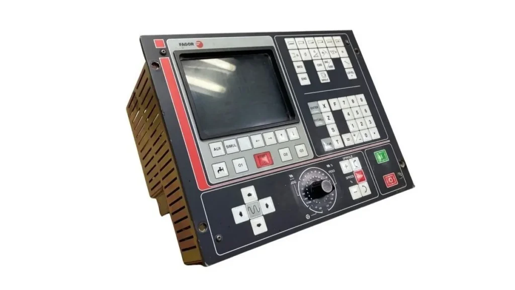
The FAGOR CNC 800T is a specialized numerical control system designed primarily for lathes (turning machines). Released in the mid-1990s and refined through software updates into the late 1990s, it remains a solid, industrial-grade controller still found on many machines. This post draws from the official Manuals to explain its architecture, how it interfaces with a machine, and the core concepts that make it function.
What the 800T Is and Who It’s For
The 800T is built for industrial environments, especially turning centers. It controls the movement of the machine axes (typically X and Z), the spindle, tools, and auxiliary functions while providing a user interface for programming, manual operation, and diagnostics.
It comes in two main physical configurations:
- Compact version: A single monoblock unit with an integrated 8-inch amber CRT screen, keyboard, and operator panel. It mounts directly on the machine control panel.
- Modular version: Three separate modules that can be placed in different locations and connected by cables up to 25 m long.
- Central Unit,
- Monitor (9-inch amber or 14-inch color),
- Keyboard
Four software/hardware variants exist (800-T, 800-TI, 800-TG, 800-TGI). All support X/Z axis control, spindle control (including constant surface speed and oriented stop), 32 tools with compensation, two electronic handwheels, and RS-232 communication. The “I” versions add an integrated PLC (PLCI). The “G” versions add graphical representation and simulation.
Hardware Overview and Connections
The Central Unit is the brain. It houses the processor, I/O interfaces, measurement inputs, and power supply. Key connectors include:
- Measurement connectors (A1, A3, A4, A5) for linear or rotary encoders on the axes and spindle.
- Analog outputs for servo drives.
- Digital I/O connectors (I/O 1 and I/O 2) for machine signals (limits, emergency stop, tool changer, coolant, etc.).
- RS-232C serial port for peripheral devices or DNC communication.
- Power input (typically 220 V AC with external fuses).
Proper grounding is critical. All modules must be connected to a central earth point, and the 24 V DC supply for digital I/O must also be referenced to machine ground. Analog signals should use shielded cable with the shield connected only at the CNC end.
The system includes galvanic isolation on digital I/O via optocouplers and external fast-acting fuses for protection against overvoltage or reverse polarity.
How the Control Actually Works
At its core, the 800T is a closed-loop servo controller. Position feedback from the axes (via linear scales or rotary encoders) is compared with the commanded path. The difference (following error) is processed through proportional and, in later software versions, feed-forward gains to generate analog velocity commands for the drives.
Key functional blocks include:
1. Axis Control
Parameters define resolution, travel limits (software and hardware), acceleration/deceleration profiles (linear or “bell-shaped”), and gains. The control supports both continuous path interpolation and manual/jog modes, including electronic handwheels. Feed-forward gain can be tuned to reduce following error during high-speed moves.
2. Spindle Control
The spindle can run in RPM mode or constant surface speed (CSS/VCC). Oriented spindle stop is available for operations such as rigid tapping or tool changes. Range changing (gearbox) is handled via digital outputs and confirmation inputs. Later software versions added linear and bell-shaped spindle acceleration ramps.
3. Tool Management
Up to 32 tools are stored in a table with geometry and wear offsets. The system supports tool measurement, inspection, and automatic tool-change cycles. A motorized tool (live tool) option exists for driven tooling.
4. Auxiliary Functions (M, S, T)
Standard ISO-style auxiliary functions are transferred to the machine via digital outputs. Handshake signals such as “M executed” and “Feed Hold” ensure synchronization between the CNC and the machine’s electrics or PLC.
Programming and Execution Modes
- Conversational / automatic cycles (drilling, grooving, threading, profiling, etc.).
- Full ISO programming via program number 99996 (user program memory).
- Manual mode with jog, handwheel, and single-block execution.
- Simulation and graphical representation (on G models).
- Special modes for parameter editing, test, and peripheral communication.
Machine parameters (hundreds of them) customize every aspect of behavior from axis polarity and resolution to spindle orientation, tool-change position, and communication settings. Two appendix tables list them both by topic and by numerical order, with cross-references to detailed explanations.
Installation and Commissioning Essentials
Before powering the unit, the machine must comply with the Machinery Directive (89/392/EEC at the time of the manual). Key steps include:
- Mounting the units with adequate clearance for ventilation and future service.
- Connecting power, ground, measurement systems, analog outputs, and digital I/O according to the pinouts in Chapter 1 and 2.
- Performing I/O tests and verifying emergency-stop circuitry.
- Setting all machine parameters (Chapters 4–6) and recording the values in the provided parameter table.
- Tuning axis gains, offsets, and reference points (Chapter 7).
- Testing tool tables, spindle orientation, and automatic cycles.
Safety features include dual emergency-stop circuits, software travel limits, and protective measures against electromagnetic interference.
Why the 800T Still Matters
Although modern CNCs offer larger screens, more axes, and advanced networking, the 800T’s strength lies in its straightforward architecture, robust industrial design, and deep configurability through parameters. Once properly set up, it delivers reliable, precise control of two-axis turning machines with optional live tooling and integrated PLC logic.
For machine builders and service technicians, the installation manual remains the definitive reference: it covers everything from physical dimensions and connector pinouts to the detailed mathematical relationships used for gain calculation, feed-forward, and reference-point setting.
Whether you are commissioning a refurbished machine or troubleshooting an existing installation, understanding the modular hardware, the closed-loop servo principles, and the extensive parameter set is the key to making the FAGOR 800T perform at its best.


