
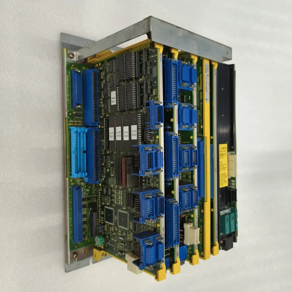
If you’ve spent enough time around FANUC-controlled machining centers, you already know how to write G-code, tune macros, and dial in feeds and speeds. But when a machine throws an unexplained alarm, refuses to cycle start, or behaves erratically during a tool change, the solution rarely lives in your NC program. It lives deeper in the control’s nervous system: the FANUC Programmable Machine Controller (PMC).
Many machinists and programmers mistakenly refer to all internal data as “variables,” but FANUC draws a clear line between G-code macro variables (#100, #500, etc.) and the PMC’s memory architecture. The latter is where the control actually talks to the machine tool. If you want to troubleshoot like a service engineer, integrate custom automation, or safely modify machine builder logic, you need to understand the five core PMC address types: X, Y, R, F, and G.
In this post, we’ll break down exactly what these signals are, how FANUC structures them in memory, how data flows during a control scan, and how to work with them safely and effectively.
The PMC Foundation: FANUC’s Built-In PLC
Before diving into individual address types, it helps to understand where they live. Every FANUC CNC control contains a built-in PLC called the PMC (Programmable Machine Controller). While the CNC handles interpolation, tool compensation, and program execution, the PMC manages everything else: safety interlocks, coolant pumps, spindle orientation, tool changers, mode selection, alarm routing, and operator panel inputs.
The PMC doesn’t use traditional PLC tags. Instead, it organizes memory into fixed address families. Each family serves a specific communication direction or function. Machine Tool Builders (MTBs) use FANUC’s Ladder III or Ladder V software to write custom logic that reads and writes these addresses. When you press a button on the pendant or a proximity switch trips, the signal travels through this architecture. Understanding it turns guesswork into systematic troubleshooting.
Decoding the Core Signal Types: X, Y, R, F, G
X Signals: Machine Inputs to PMC
Direction: Machine Hardware → PMC
Access: Read-only from the PMC perspective
Purpose: Physical state reporting
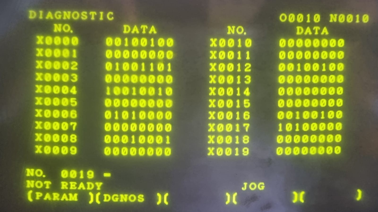
X addresses represent discrete inputs wired from the machine tool to the PMC. These include limit switches, door interlocks, pressure sensors, tool presence switches, and operator pushbuttons. The PMC continuously polls these addresses to know the physical state of the machine.
Example: X1008.3 might indicate “Chuck Closed.” If the ladder logic expects this bit high before allowing spindle rotation, but the bit stays low, the control will block the cycle and typically raise an alarm. X signals are read-only in the ladder; you cannot force them from the PMC. If an X signal isn’t behaving as expected, the fault lies in wiring, sensors, or mechanical alignment.
Y Signals: PMC Outputs to Machine
Direction: PMC → Machine Hardware
Access: Write-only from the PMC perspective
Purpose: Actuating physical components
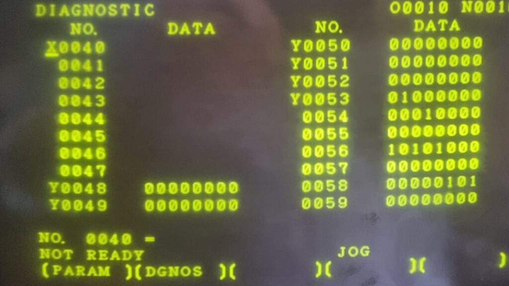
Y addresses control relays, solenoid valves, indicator lights, contactors, and other external hardware. When ladder logic evaluates a condition and sets a Y bit, the PMC energizes the corresponding output circuit.
Example: Y1012.0 could command “Hydraulic Pump Start.” Unlike X signals, Y bits are driven by the ladder. If a Y output fails to activate, the issue typically resides in the PMC logic, a blown output fuse, a failed relay, or a shorted coil. Y signals should never be manually forced during normal operation unless you fully understand the downstream hardware state.
F Signals: CNC Status to PMC
Direction: CNC → PMC
Access: Read-only from the PMC perspective
Purpose: CNC operational state and diagnostics
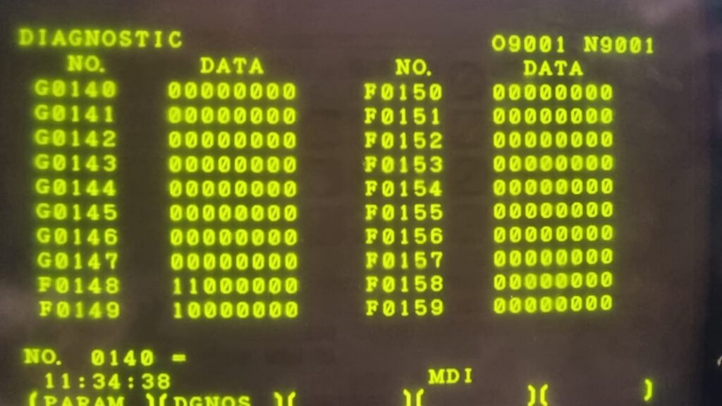
F addresses are the CNC’s way of broadcasting its internal status to the PMC. These are heavily documented in FANUC’s Signal Manuals and cover everything from operating mode (F0.0 – F0.3), spindle rotation status, axis interpolation completion, alarm states, macro variable conditions, and program execution flags.
Example: F1.2 indicates spindle forward rotation command active. F0.7 signals that the control is in MDI mode. The PMC reads these continuously to make logic decisions. For instance, a ladder rung might read F0.2 (Auto mode) and F1.2 (Spindle FWD) before enabling a chip conveyor. Because F signals reflect the CNC’s internal state, they cannot be overwritten by the PMC. They are the source of truth for what the control is actually doing.
G Signals: PMC Commands to CNC
Direction: PMC → CNC
Access: Write-only from the PMC perspective
Purpose: Control and command routing
G addresses are the reverse of F signals: they allow the PMC to send commands to the CNC. These include cycle start (G7.2), feed hold (G8.5), reset (G8.0), mode selection, override requests, and program stop commands. Writing to G signals is powerful but dangerous. An incorrectly timed G signal can interrupt machining, trigger unintended axis motion, or corrupt program execution.
Example: When the operator presses “Cycle Start,” the panel input updates an X bit. The ladder validates safety conditions, then sets G7.2. The CNC detects the high state and begins executing the NC program. Machine tool builders carefully gate G signals with interlocks, timers, and state flags to prevent accidental activation. Never write to reserved G addresses without consulting the official FANUC signal documentation for your specific control series.
R Registers: Internal PMC Memory
Direction: Internal PMC ↔ Internal PMC
Access: Read/Write
Purpose: Logic flags, temporary storage, sequencing, and user data
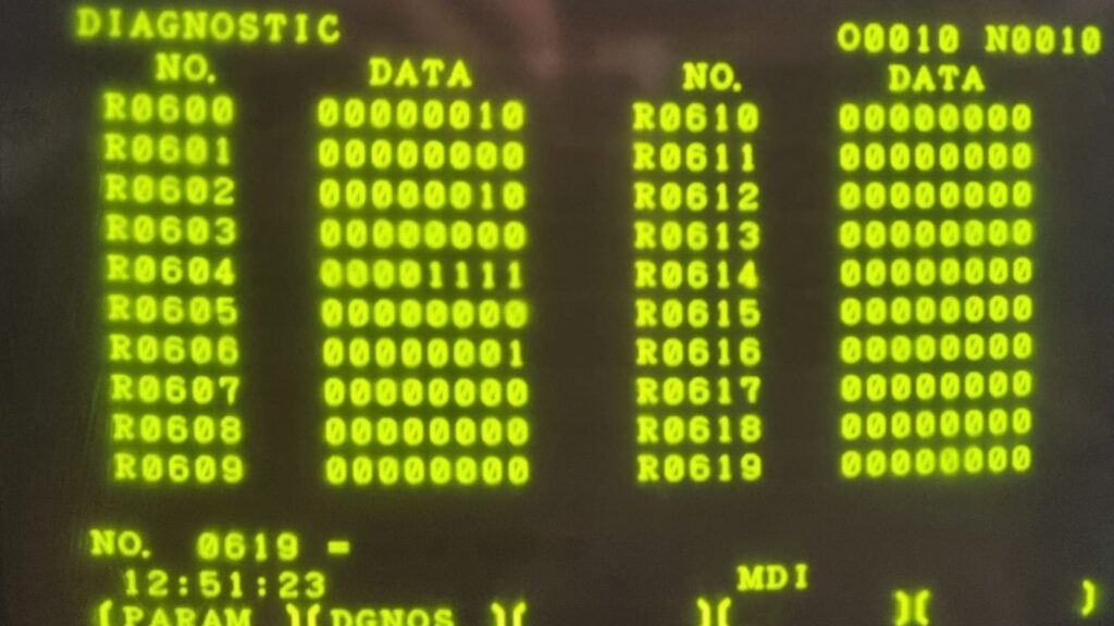
R addresses are the workhorses of PMC ladder logic. They function like internal relays, holding bits that track machine states, sequence steps, timer completion, counter values, and custom flags. Unlike X/Y/F/G, R registers are entirely internal to the PMC. They do not directly connect to hardware or the CNC.
Example: R500.0 might mean “Tool Change Sequence Active.” R500.1 could mean “Tool Clamp Confirmed.” R1000 through R1999 are often reserved by MTBs for custom data storage or macro integration. R registers can be addressed at the bit level (R500.3) or word level (R500 for 16-bit data). Some R addresses retain their values across power cycles (non-volatile), while others reset on startup. MTBs define which ranges are persistent based on the control’s memory configuration.
Memory Architecture and Data Flow
FANUC’s PMC memory isn’t a flat RAM space. It’s a structured, cyclically scanned architecture designed for deterministic real-time control. Here’s how it operates under the hood:
The Scan Cycle
- Input Read: The PMC samples all X signals and physical inputs.
- CNC Sync: The CNC writes current status to F registers. The PMC reads them.
- Ladder Execution: The PMC processes the ladder logic top-to-bottom, evaluating X, F, and R bits, then computing new Y and G states.
- Output Write: Y signals drive external hardware. G signals are sent to the CNC.
- R Update: Internal flags and counters are updated for the next scan.
This cycle repeats continuously, typically in 8–32 milliseconds depending on control series and ladder size. The speed is why understanding data flow matters: a bit set in one rung may not affect another until the next scan. Poorly structured logic can cause race conditions or missed states.
Bit vs. Word Addressing
FANUC PMC uses byte-aligned memory, but most signals are accessed at the bit level (Address.Bit). For example, F0.0 through F0.7 occupy one byte. Word-level access (R100) reads 16 consecutive bits as an integer. This is crucial when transferring data between the PMC and macro variables using system variables like #1032 or #1100 series. Misalignment (e.g., reading a word that crosses a hardware boundary) will return corrupted data.
Reserved vs. User Areas
FANUC and MTBs partition memory strictly. Lower ranges of F and G are reserved for core CNC functions. Higher ranges may be available for custom logic. R registers are similarly partitioned: some are volatile, some non-volatile, some reserved for tool management or macro communication. Overwriting reserved addresses can cause erratic behavior, lost parameters, or control faults. Always cross-reference your control’s Maintenance Manual and Signal Manual before modifying ladder logic.
Practical Applications and Best Practices
Mastering X, Y, R, F, G architecture transforms how you interact with FANUC controls. Here’s how to apply it safely and effectively:
1. Signal Tracing Over Guesswork
When an alarm triggers, don’t just restart the machine. Use the PMC I/O monitor screen (SYSTEM > PMC > PMCDGN > STATUS) to trace the exact signal chain. Is the door closed switch actually reporting to X? Is the PMC writing the correct Y to the solenoid? Is an F signal missing that the ladder expects? Signal tracing isolates hardware, logic, or CNC faults in minutes.
2. Document Your R Registers
Machine builders often leave R registers undocumented, turning troubleshooting into archaeology. Create a signal map: R500.0 = TC Active, R500.1 = TC Complete, R600 = Custom Part Counter. Store it in your maintenance binder and backup folder. Future you (and your colleagues) will thank you.
3. Never Force F/G Without Context
The PMC monitor allows manual bit forcing, but forcing F or G signals bypasses safety interlocks. Forcing G7.2 (Cycle Start) while a tool is unclamped can crash the spindle. Only force signals for diagnostic purposes, and always revert changes before running production.
4. Bridge PMC and Macro Variables Safely
G-code macro variables (#) and PMC registers (R, F, G) live in different memory spaces. To pass data between them, use FANUC’s system variables. For example, #1000 series reads/writes PMC data registers, while #3000 triggers alarms from macros. Always validate data ranges and scan timing when crossing the CNC/PMC boundary.
5. Backup Before Every Ladder Change
PMC ladder modifications require a full backup: parameters, pitch error, macro programs, and the .LAD ladder file. Use FANUC Ladder III/IV with Ethernet or PCMCIA/USB transfer. Test changes in simulation mode when possible. A single misplaced G signal can brick a machine until the ladder is restored.
Conclusion
FANUC’s X, Y, R, F, and G memory architecture isn’t just a list of addresses. It’s a meticulously engineered communication protocol that bridges code, control, and physical machinery. While G-code tells the machine what to cut, the PMC tells it when and how to do it safely. Understanding these signal types, their read/write boundaries, and how they flow through the scan cycle elevates you from a part programmer to a true CNC integrator.
The best way to learn is hands-on. Load a safe ladder backup, open the PMC monitor, trigger inputs, watch outputs update, and trace how R registers hold state. Cross-reference everything with FANUC’s official signal manuals. With practice, you’ll diagnose alarms faster, customize automation confidently, and keep your machines running at peak reliability. In modern manufacturing, that’s not just a technical skill it’s a competitive advantage.


