
Introduction
Precision and repeatability are at the heart of quality CNC machining. One critical process that ensures both is the FANUC Zero Return Procedure the method by which a machine establishes its reference positions and aligns its coordinate system for accurate motion control.
This guide covers the importance of Zero Return, how FANUC systems manage reference points, the difference between absolute and incremental encoders, and a complete step-by-step procedure to set up the home position correctly.
What Is FANUC Zero Return?
FANUC Zero Return (also called Machine Home Positioning or Reference Point Return) is the process of establishing a known, fixed reference point on each machine axis. When a FANUC CNC powers on especially after a full shutdown the control must know exactly where each axis is located in physical space. Zero Return provides that knowledge.
Without an accurate Zero Return:
- The CNC cannot correctly interpret G-code coordinates.
- Tool changes may collide with the workpiece or fixture.
- Work offsets (G54–G59) become unreliable.
- Soft limit alarms and overtravel errors can occur.
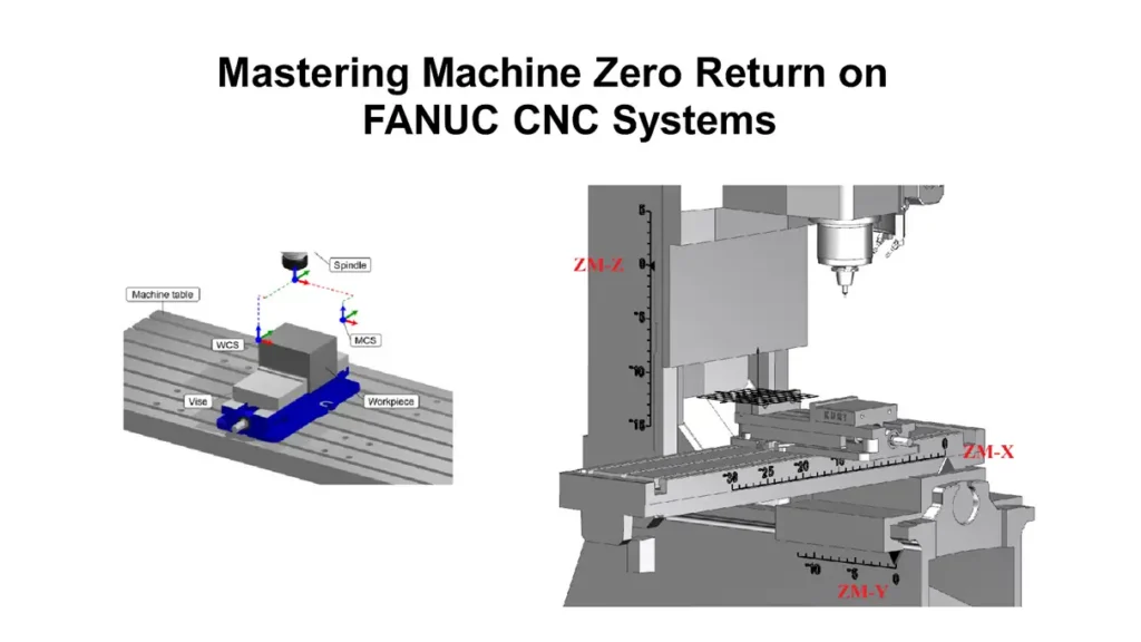
Zero Return establishes Machine Zero (also called Machine Reference Point), the origin of the machine coordinate system. All tool movement, work offsets, and program execution are ultimately referenced to this point.
Absolute vs. Incremental Encoders
The Zero Return procedure depends heavily on which type of encoder your FANUC servo motor uses.
Important: If the encoder backup battery voltage drops below the required level and is not replaced in time, the machine will lose its reference position, requiring a manual Zero Return to reestablish machine zero.
For a detailed introduction to FANUC encoders, see: [What is a FANUC Encoder? – A Comprehensive Guide: 4 Types, Features, and Applications].
Absolute Position Encoders (A-Type)
- Retain position data even when the machine is powered off.
- Do not require a manual Zero Return at every startup.
- Depend on a backup battery if the battery dies, the machine loses its reference position and requires a manual Zero Return.
- All FANUC βi-series and most modern αi-series motors use absolute encoders by default.
Incremental Position Encoders (I-Type)
- Do not retain position data when the machine is powered off.
- Require a manual Zero Return every time the CNC system restarts.
- Use a physical reference marker (index pulse) on the encoder disc to reestablish the zero position.
Impact on the Zero Return Procedure
| Encoder Type | Zero Return at Power-On | Battery Required | Notes |
|---|---|---|---|
| Absolute (A) | Usually not needed | Yes (backup) | Required only after battery replacement, encoder swap, or parameter reset |
| Incremental (I) | Always required | No | Must be performed after every power cycle |
FANUC Zero Return Procedure : Step-by-Step Guide
Prerequisites
Before starting:
- 1.Confirm the machine is in MDI or JOG mode : never attempt Zero Return in AUTO mode.
- 2.Check for alarms : clear any existing alarms (especially overtravel alarms, alarm 300, or servo alarms).
- 3.Verify encoder battery voltage (absolute encoders) : replace if below specification (typically < 3.0V).
- 4.Ensure adequate clearance : all axes must be able to travel toward the reference point without obstruction.
Method 1: Standard Reference Point Return (Incremental Encoders or Initial Setup)
This is the standard method when using incremental encoders, or after replacing a battery/encoder on an absolute system:
- Switch to Zero Return mode : select the ZRN (Zero Return) mode on the machine’s mode selector switch.
- Select an axis : press the axis selection button (+X, +Y, +Z, etc.) for the axis you want to return.
- Jog toward the reference point : the machine will move toward the deceleration dog (reference switch) at rapid rate.
- Deceleration : when the axis hits the deceleration dog, the feedrate drops to a slow speed.
- Index pulse detection : after clearing the dog, the machine searches for the encoder’s index pulse to establish the exact zero position.
- Repeat for each axis : perform the procedure for every axis (X, Y, Z, and any additional axes).
- Verify : the Zero Return complete lamp/LED should illuminate for each axis. The machine coordinate display should show the reference position value (typically 0.000 or a configured offset).
Method 2: Setting Home Position via Parameter 1815 (Absolute Encoders)
When using absolute encoders and the machine has lost its reference (e.g., after battery replacement or encoder replacement), you must manually establish the home position and set it via Parameter 1815.
Procedure:
- Manually jog the axis to the desired home position using the HANDLE or JOG mode. Ensure this is the correct mechanical reference point.
- Set Parameter 1815#4 (APZx) = 1 to mark the current position as the absolute encoder zero point.
- Power off the CNC completely (main breaker or disconnect switch).
- Power back on the machine will now treat the position where APZ was set as Machine Zero.
If Parameter 1815#4 Cannot Be Set to 1:
This typically happens when the encoder has not yet detected a valid position. Follow these steps:
- Manually jog the axis at least one full motor revolution (or more) from its current position. This ensures the encoder reads enough counts to establish a valid position.
- Set Parameter 1815#5 (APCx) = 0 (temporarily disable absolute position detection).
- Set Parameter 1815#4 (APZx) = 1 (mark the current position as zero).
- Set Parameter 1815#5 (APCx) = 1 (re-enable absolute position detection).
- Power off and restart the CNC.
Best practice: When using an absolute position detector for the first time, after a battery replacement, or after an encoder swap, set APZx (1815#4) to 0 first. After manually moving the axis to the correct reference point (or performing a standard reference return), set APZx back to 1. The control will automatically validate the position correspondence.
Parameter 1815 Quick Reference
| Parameter Bit | Name | Value | Meaning |
|---|---|---|---|
| 1815#5 | APCx | 1 | Absolute position encoder in use |
| 1815#5 | APCx | 0 | Incremental (relative) position encoder in use |
| 1815#4 | APZx | 1 | Absolute encoder zero return successfully set |
| 1815#4 | APZx | 0 | Home position not set Alarm 300 will be generated |
| 1815#1 | OPTx | 1 | Full closed-loop mode enabled (linear scale) |
| 1815#1 | OPTx | 0 | Semi-closed-loop mode enabled (rotary encoder only) |
Grid Shift Adjustment (Parameter 1850)
After performing Zero Return, the machine may not land exactly where you want the reference point to be. Instead of physically moving the deceleration dog, you can fine-tune the home position using Grid Shift.
- Parameter 1850 (GRDSx) sets the grid shift value in detection units for each axis.
- A positive value shifts the reference point in the positive direction; a negative value shifts it negative.
- After changing Parameter 1850, you must re-perform the Zero Return procedure for the change to take effect.
This is especially useful during initial machine setup or after mechanical maintenance.
Soft Limit Considerations
When the home position is incorrect or has not been set:
- Alarm 500 / 501 (Overtravel) may occur because soft travel limits are calculated from Machine Zero.
- Parameters 1320 (positive soft limit) and 1321 (negative soft limit) define the travel range. An incorrect home position makes these limits unreliable.
- Always verify soft limit values in the parameter manual for your specific machine after changing the home position.
Causes of Zero Return Failure and Troubleshooting
If the Zero Return procedure fails, work through these common causes in order:
1. Insufficient Motor Rotation (Absolute Encoders)
The motor must rotate at least one full revolution before the encoder can establish a valid position.
Solution: Manually jog the axis one full turn or more, then reattempt the Zero Return or APZ setting.
2. Encoder Power Supply Issue or Damaged Wiring
The encoder requires a stable 6V DC power supply. If the encoder cable is damaged, disconnected, corroded, or has insufficient voltage, the machine will fail to establish the reference position.
Solution:
- Check the encoder power lines with a multimeter to confirm a stable 6V output at the encoder connector.
- Inspect the encoder cable for cuts, abrasion, pinched sections, or loose connectors.
- Check connector pins for corrosion or bent contacts.
- Replace any damaged cables with the correct FANUC-specified shielded cable.
3. Faulty or Degraded Encoder
If the encoder itself is damaged or malfunctioning, it will not correctly store or relay position data, causing persistent zero return failure.
Solution:
- Try disconnecting and reconnecting the encoder cable at both the motor and drive ends.
- Check for error codes on the servo amplifier (SVPM / SVM) that indicate encoder communication faults.
- If the issue persists, replace the encoder. For absolute encoders, you will need to reperform the 1815#4 procedure after replacement.
4. Deceleration Dog / Reference Switch Malfunction
On incremental encoder systems, the machine relies on a physical deceleration switch (dog) to slow the axis before finding the index pulse. If this switch is stuck, misaligned, or electrically faulty, the axis will not decelerate and the reference return will fail or overshoot.
Solution:
- Check the deceleration dog switch and bracket for physical damage or misalignment.
- Test the switch with a multimeter — it should toggle cleanly when the cam engages it.
- Verify the signal status on the diagnostic page (DGN 124.x or equivalent for your control) while manually pressing the switch.
- Adjust or replace the switch if needed.
5. Soft Limit or Overtravel Alarm Preventing Movement
If the axis is already at or beyond a soft limit, the machine may refuse to jog toward the home position.
Solution:
- Hold the P + CAN keys during power-on to temporarily override soft limits (on supported FANUC controls).
- Or, set parameter 1320/1321 to wider values temporarily, perform the Zero Return, then restore the correct limits.
6. Servo Alarm or Emergency Stop Active
Any active servo alarm (SV0301, SV0368, etc.) or E-stop condition will prevent the Zero Return mode from functioning.
Solution:
- Clear all alarms first.
- Check the servo amplifier for LED error codes and consult the FANUC maintenance manual.
- Ensure the emergency stop circuit is closed and the E-stop button is released/ reset.
Conclusion
The FANUC Zero Return Procedure is a fundamental process in CNC machining, ensuring precision, safety, and machine reliability. By understanding the difference between absolute and incremental encoders , and knowing how to correctly set and verify Parameter 1815 operators can prevent common issues like position loss, overtravel alarms, and misalignment errors.
Key takeaways:
- Absolute encoder users: Monitor battery voltage. Replace promptly to avoid losing the reference position.
- Incremental encoder users: Perform Zero Return at every power-on without exception.
- After any encoder or battery service: Always re-set the home position using the 1815#4 procedure and verify with a test program.
- Use Grid Shift (Parameter 1850) to fine-tune the reference position without mechanical adjustment.
- Regular maintenance encoder battery checks, cable inspections, and deceleration dog verification will keep your FANUC CNC machine operating accurately and efficiently.


