
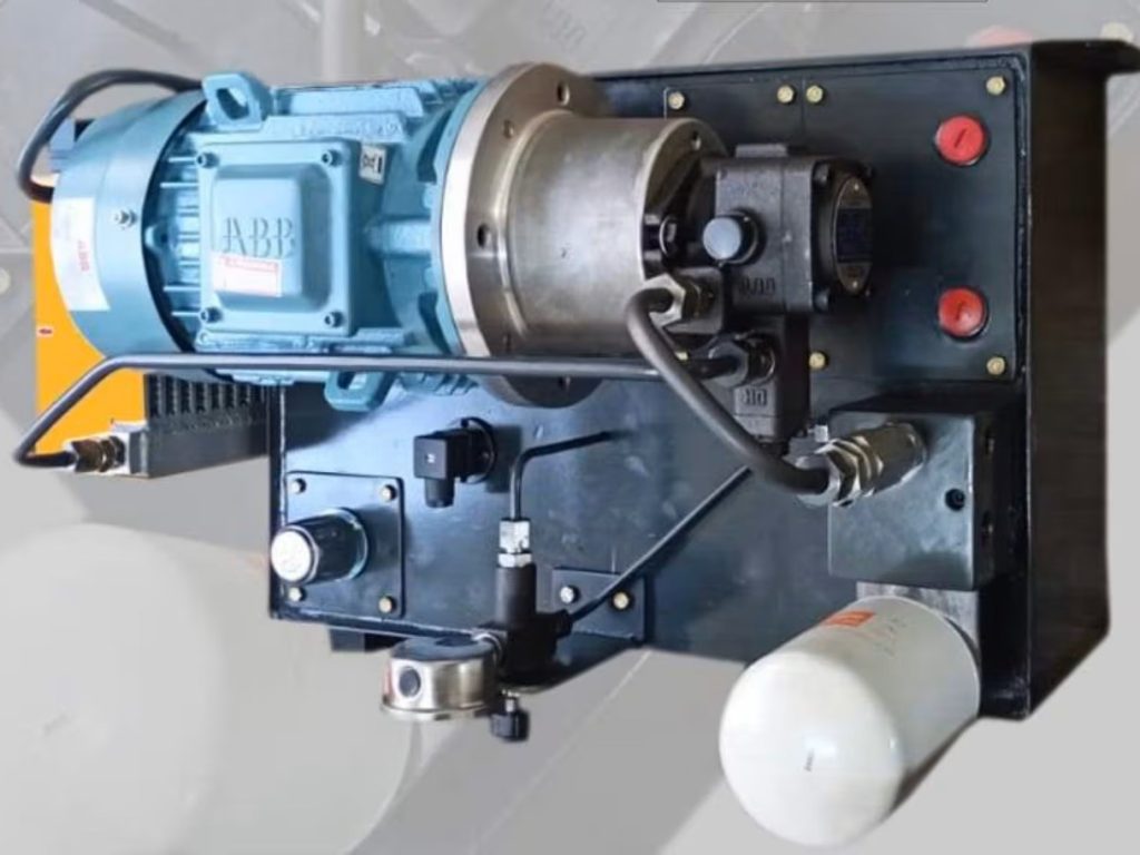
In the high-stakes world of precision manufacturing, machine tools like CNC lathes, machining centers, surface grinders, and hydraulic presses rely on a delicate balance of brute force and microscopic accuracy. While electric motors drive the spindles and ball screws, it is often the Hydraulic Power Pack that handles the heavy, critical tasks clamping workpieces, actuating tool changers, counterbalancing heavy rams, and moving massive machine slides.
But a hydraulic system is only as good as its maintenance. In this comprehensive guide, we will break down the anatomy of a machine tool power pack, explain its working principles, and provide a crucial maintenance checklist to prevent costly downtime.
The Anatomy: Main Components Power Pack
A power pack isn’t just a motor and a tank; it’s a complex assembly of precision parts. In a machine shop environment, where coolant mist, metal chips (swarf), and temperature fluctuations are constant threats, every component plays a vital role.
1. The Power Source & Drive
- Electric Motor (3 Phase): The primary driver. In machine tools, these are often designed for continuous duty cycles or frequent start-stops to keep the hydraulics ready for rapid tool changes and clamping sequences.
- Coupling: This connects the motor shaft to the pump shaft. A flexible, vibration-dampening coupling is critical here to prevent motor vibrations from transferring to the pump, which could cause premature wear or affect machining precision.
- Hydraulic Pump: The muscle of the unit. Machine tools typically use Gear, Vane, or Piston pumps. Vane pumps are particularly popular in machine shops because they operate quietly and provide a smooth, low-pulsation flow, ensuring the smooth movement of machine slides.
2. The Reservoir & Filtration (The First Line of Defense)
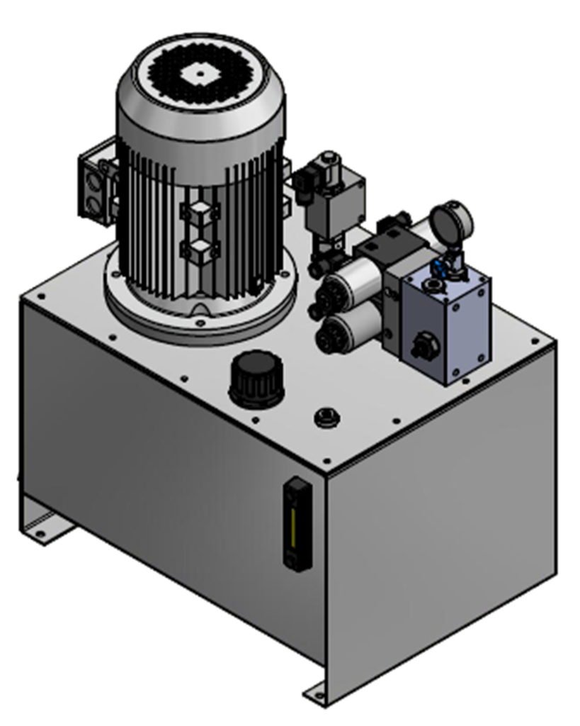
- Hydraulic Tank (Reservoir): The large steel box at the base. It stores the hydraulic oil and helps dissipate heat. In a machine shop, this tank must be heavily sealed to prevent coolant and swarf from entering.
- Suction Filter: Located inside the tank (often at the end of the suction line), this is a coarse filter that ensures the pump doesn’t suck up large debris.
- Return Filter: The critical blue canister seen in the diagram. As oil returns from the machine’s cylinders, it may carry fine metal particles from wear and tear. This high-micron filter traps them, protecting sensitive servo valves from clogging.
- Breather (Air Filter): As oil levels change and temperatures fluctuate, the tank “breathes.” The breather filters incoming air to keep shop dust and moisture out of the reservoir.
- Oil Level Indicator: A sight glass on the side of the tank. It allows operators to quickly verify fluid levels during daily walk-arounds.
- Cooler (Optional but Recommended): Hydraulic systems generate heat. An air or water cooler maintains optimal oil viscosity, which is crucial for maintaining tight tolerances in precision machining.
3. Control & Safety
- Directional Control Valve (DCV): The “traffic cop.” In a CNC machine, solenoid-operated DCVs are used to automatically sequence operations—like unclamping a part, moving a tailstock, or engaging a chuck.
- Relief Valve: The ultimate safety net. Machine tools have delicate castings and components. The relief valve is set to a specific pressure limit. If a clamp hits a hard stop, this valve opens to release pressure, preventing blown hoses or cracked machine bases.
- Pressure Gauge: The dashboard for the maintenance technician, showing the current system pressure to ensure clamping forces are within spec.
How It Works: The Working Principle in a Machine Tool
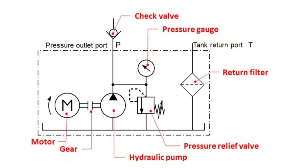
Looking at the “Hydraulic Circuit” schematic at the bottom of the diagram, we can trace the journey of the hydraulic fluid during a typical machining cycle:
- The Start: The Electric Motor turns on (triggered by the machine’s PLC), driving the Hydraulic Pump.
- The Suction: The pump creates a vacuum, drawing oil from the Hydraulic Tank through the Suction Filter.
- The Pressurization: The pump converts mechanical energy into hydraulic energy, creating a steady stream of pressurized oil.
- The Action: The pressurized oil travels to the Directional Control Valve (DCV). The machine’s computer signals the DCV to shift, sending oil to a hydraulic cylinder. This cylinder might clamp a heavy workpiece onto the table or pull the drawbar to release a cutting tool.
- The Return: Once the action is complete, the oil flows back to the tank. Crucially, it passes through the Return Filter, catching microscopic metal fines generated by the machine’s moving parts.
- The Safety Check: Throughout the cycle, the Relief Valve monitors the pressure. If the workpiece is too hard and the clamp cannot move further, pressure spikes. The relief valve diverts the excess oil back to the tank, protecting the pump from damage.
The Machine Shop Survival Guide: Hydraulic Maintenance Tips
In a machine shop, a failed hydraulic power pack doesn’t just mean a broken machine; it means scrapped parts, missed deadlines, and expensive emergency repairs. Because hydraulic systems are highly sensitive to contamination, proactive maintenance is non-negotiable.
Here are the essential maintenance tips to keep your machine tool power packs running at peak performance:
1. Master Your Filtration Protocol
- Change Return Filters Regularly: The return filter (the blue canister) is your system’s kidneys. Check the machine’s manual for the recommended interval, but in a high-production shop, check it more often. Many return filters have a visual or electrical clogging indicator—never ignore it.
- Inspect the Suction Filter: A clogged suction filter causes the pump to “cavitate” (starve for oil), which sounds like marbles rattling inside the pump and will quickly destroy it. Clean or replace the suction strainer during annual oil changes.
2. Fluid Management and Oil Analysis
- Don’t Just Top Off, Test: Never add new oil to old, degraded oil without testing it first. Use a portable particle counter or send a sample to a lab for oil analysis. This will tell you if your oil is breaking down, if water (coolant) has mixed in, or if there is excessive metal wear.
- Change Oil on Schedule: Even with good filters, hydraulic oil degrades over time due to heat and shear. Follow the OEM’s schedule for complete fluid changes.
3. Protect the Breather
- The Most Overlooked Component: The breather cap is often ignored until the pump starts whining. If the breather clogs with shop dust, the tank creates a vacuum as the pump sucks oil out, leading to pump cavitation. Check and clean or replace the breather element every 6 months.
4. Monitor Temperature and Pressure
- Keep it Cool: Hydraulic oil should ideally operate between 110°F and 130°F (43°C – 54°C). For every 15°F increase above this range, the life of your hydraulic seals and hoses is cut in half. If your oil is running hot, check the cooler for dust buildup or verify the relief valve isn’t stuck open (which dumps high-pressure oil back to the tank, generating massive heat).
- Verify Pressure: Use the Pressure Gauge to ensure the system is holding the correct pressure. A dropping pressure gauge usually indicates internal leaks in the DCV spools or worn pump vanes.
5. Leak and Hose Inspection
- Look for “Weeping”: High-pressure hydraulic hoses degrade from the inside out. Look for any oily residue or “weeping” around hose crimps and fittings.
- Check for Blisters: If a hydraulic hose has a soft spot or a blister, replace it immediately. A burst high-pressure hose in a machine shop can inject oil into the skin (a severe medical emergency) and spray hot oil over electrical components.
Conclusion
The Hydraulic Power Pack is the muscle behind the precision of your machine tools. By understanding its anatomy from the 3-phase motor and vane pump to the critical return filter and relief valve you can better diagnose issues before they cause catastrophic failures.
Implementing a strict maintenance routine focused on filtration, fluid quality, and temperature control will not only extend the life of your power pack but also ensure your machine tools continue to hold tight tolerances and produce high-quality parts for years to come.


