
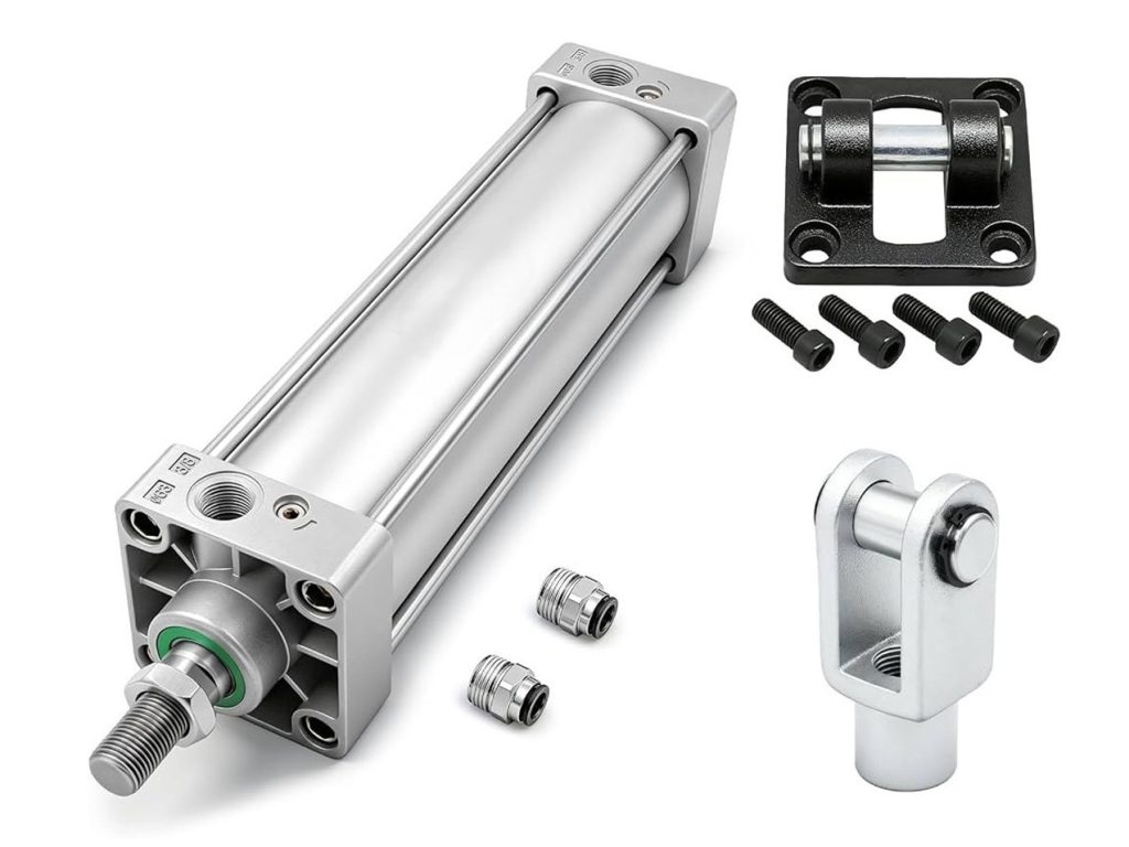
In the world of industrial automation and manufacturing, few components are as fundamental or as versatile as the pneumatic cylinder. Also known as an air cylinder, this unassuming mechanical actuator is the workhorse behind countless machines, providing reliable, clean, and efficient linear motion.
Whether you are designing a high-speed packaging line, a robotic assembly cell, or a heavy-duty clamping system, understanding pneumatic cylinders is essential. This comprehensive guide breaks down everything you need to know about how they work, their core components, the different types available, and how to select the right one for your application.
What is a Pneumatic Cylinder and How Does It Work?
At its core, a pneumatic cylinder is a mechanical device that converts the potential energy of compressed air into kinetic energy, producing linear force and motion.
The basic principle is straightforward: compressed air is introduced into a sealed cylindrical chamber, increasing the internal pressure. This pressure pushes against a movable piston, which in turn drives a connected piston rod outward or inward. This linear motion is then transferred to an external load to perform work—such as pushing, pulling, lifting, clamping, or indexing.
Because they use compressed air rather than hydraulic fluid or electricity, pneumatic cylinders offer distinct advantages:
- Clean Operation: Air leaks do not contaminate the environment, making them ideal for food processing, pharmaceuticals, and cleanrooms.
- High Speed: They can achieve rapid cycle times and fast acceleration.
- Safety: They are inherently explosion-proof and can safely stall under overload without damaging the system.
- Simplicity: They require less complex infrastructure than hydraulic systems and generate minimal heat.
The Anatomy of a Pneumatic Cylinder
To select and maintain a pneumatic cylinder effectively, it helps to understand its internal architecture. While designs vary, most standard cylinders share these critical components:
- Cylinder Barrel (Bore): The main pressure vessel, typically machined from aluminum, stainless steel, or coated steel. It houses the internal components and must be perfectly smooth to ensure an airtight seal and frictionless piston movement.
- End Caps: Located at the front (rod end) and rear (cap end) of the barrel, these enclose the pressure chamber. They contain the air inlet and exhaust ports.
- Piston: A disc that fits snugly inside the barrel, dividing the cylinder into two separate chambers. The surface area of the piston directly determines the force output of the cylinder (Force = Pressure × Area).
- Piston Rod: A hardened, often chrome-plated steel rod attached to the piston. It extends outside the cylinder to connect with the machine component being moved.
- Seals and O-Rings: Made from durable elastomers (like NBR or polyurethane), these prevent compressed air from leaking between the chambers or out of the cylinder.
- Guide Rings (Wear Bands): Mounted on the piston, these low-friction bands prevent metal-to-metal contact between the piston and the barrel, absorbing radial loads and extending service life.
- Cushioning Mechanisms: Adjustable or fixed cushions at the end of the stroke trap and exhaust air gradually, slowing the piston down to prevent harsh, damaging impacts at the end caps.
- Sensors: Magnetic reed switches or solid-state Hall-effect sensors can be mounted on the cylinder barrel to detect the piston’s position, providing vital feedback to a PLC for automated control.
- Tie Rods: Threaded steel rods that clamp the end caps to the barrel. They provide structural integrity under high pressure and are a hallmark of NFPA and ISO standard cylinders.
Types of Pneumatic Cylinders
Pneumatic cylinders are not one-size-fits-all. They are categorized based on their actuation method, physical design, and intended application.
1. Single-Acting Cylinders
These cylinders use compressed air to move the piston in one direction (either extend or retract). A built-in mechanical spring (or sometimes gravity/external load) returns the piston to its home position when the air pressure is released.
- Best for: Clamping, ejection, or safety-critical applications where the cylinder must default to a safe position upon air loss.
- Limitations: The spring occupies space, limiting stroke length, and consumes some of the air pressure, reducing overall output force.
2. Double-Acting Cylinders
The most common type in industrial automation. Compressed air is alternately supplied to both the cap end and the rod end of the cylinder, powering both the extension and retraction strokes.
- Best for: Applications requiring force and control in both directions, such as lifting, pressing, and precise positioning.
- Note: Extension force is always slightly higher than retraction force because the piston rod displaces some of the surface area on the rod side.
3. Rodless Cylinders
Ideal for long strokes in tight spaces, rodless cylinders eliminate the external piston rod. Instead, the internal piston is mechanically or magnetically coupled to an external carrier or platform that slides along the length of the cylinder body.
- Band Cylinders: Use a sealed steel or polyurethane band running through a slot in the barrel to connect the piston to the carrier.
- Cable Cylinders: Use a high-tension cable routed over pulleys at the end caps. Compact and cost-effective, but less rigid.
- Magnetically Coupled Cylinders: Use strong permanent magnets to drive the external carrier through the cylinder wall. Completely sealed, making them perfect for cleanrooms or environments where rod wiper contamination is a concern.
4. Specialty Cylinders
- Tandem (Multi-Force) Cylinders: Two or more cylinders stacked in series on a single rod. They multiply the output force (e.g., double or triple) without increasing the bore diameter, ideal for high-force applications in confined spaces.
- Telescopic Cylinders: Feature nested sleeves that extend sequentially, providing a very long stroke from a compact retracted length.
- Rotary Actuators: Convert pneumatic energy into rotational motion (torque) rather than linear motion, commonly using a rack-and-pinion or vane design for indexing, sorting, or valve operation.
- Welded Cylinders: The end caps are welded directly to the barrel, eliminating tie rods. This creates a highly compact, robust cylinder suited for mobile equipment or harsh environments, though they are harder to service.
Mounting Styles and Their Impact
How you mount a pneumatic cylinder is just as critical as the cylinder itself. Improper mounting can lead to premature seal wear, rod bending, and catastrophic failure. Mounting styles generally fall into three categories:
Centerline Mounts
The force is applied directly along the central axis of the cylinder, minimizing bending moments and shear stress on mounting hardware.
- Tie-Rod Mounting: The extended tie rods are used to bolt the cylinder directly to a machine surface. Highly versatile and common.
- Flange Mounting: A square or rectangular flange is attached to the front or rear cap. Excellent for absorbing heavy thrust loads, but intolerant of misalignment.
- Centerline Lug Mounting: Lugs are machined into the mid-point of the cylinder barrel, allowing it to be pinned or bolted down while maintaining centerline force distribution.
Side Mounts
The cylinder is mounted offset from its centerline, either via feet on the barrel or brackets on the side of the end caps.
- Consideration: Side mounts create a moment load (a rotational force) on the mounting bolts. They are best suited for short-stroke, low-speed applications or when guided by external linear rails to prevent rod binding.
Pivot Mounts
These allow the cylinder to change its angle of alignment during the stroke, accommodating applications where the load moves in an arc.
- Clevis Mounts: A U-shaped bracket with a pin allows the cylinder to pivot in a single plane.
- Trunnion Mounts: Cylindrical pivots are mounted on the cylinder’s end caps or barrel, allowing it to swing smoothly. Trunnion mounts handle higher loads than clevis mounts.
Selection Criteria and ISO Standards
Choosing the right pneumatic cylinder requires evaluating several key parameters:
- Bore Size: Determines the force output. Calculate the required force (including a 20-30% safety margin for friction and load variations) and select a bore that can deliver it at your available shop air pressure (typically 80–100 psi).
- Stroke Length: The distance the piston must travel. Keep it as short as possible to minimize buckling risk and air consumption.
- Operating Pressure: Ensure the cylinder’s rated pressure exceeds your system’s maximum pressure.
- Environment: Choose stainless steel or coated barrels and specialized seals for corrosive, washdown, or high-temperature environments.
The Role of ISO Standards
To ensure global interoperability, many pneumatic cylinders are built to ISO standards. This guarantees that cylinders from different manufacturers will share identical mounting dimensions, port sizes, and rod ends, making replacement and sourcing seamless.
- ISO 15552: The current standard for general-purpose, tie-rod pneumatic cylinders (replacing the older ISO 6431 and VDMA 24562). Covers bore sizes from 32mm to 320mm.
- ISO 21287: The standard for compact pneumatic cylinders, offering a shorter overall length for space-constrained applications.
- ISO 6432: The standard for miniature, round-body stainless steel cylinders (8mm to 25mm bore).
Conclusion
Pneumatic cylinders remain a cornerstone of modern industrial automation due to their simplicity, reliability, and cost-effectiveness. By understanding the differences between single- and double-acting designs, recognizing the value of rodless or tandem configurations, and selecting the appropriate mounting style and ISO standard, engineers and maintenance professionals can optimize machine performance and minimize downtime.
When specifying a pneumatic cylinder, always consult with reputable manufacturers or suppliers. They can provide valuable insights into custom modifications, material compatibility, and system integration, ensuring your automation setup runs smoothly for years to come.


