In the world of industrial automation, Programmable Logic Controllers (PLCs) serve as the nervous system of manufacturing and processing facilities. At the heart of PLC programming lies ladder logic a graphical programming language that has stood the test of time since the 1960s. Despite advances in technology, ladder logic remains the most widely used PLC programming language in industrial settings. Let’s explore why this seemingly simple language continues to power complex automation systems worldwide.
What Exactly Is Ladder Logic?
Ladder logic gets its name from its visual structure it resembles a ladder with two vertical “rails” representing power supply lines (typically labeled L1 and L2) and multiple horizontal “rungs” representing individual control circuits.
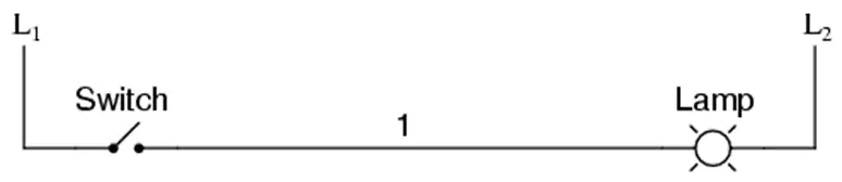
Unlike traditional programming languages that use text-based code, ladder logic uses graphical symbols that represent electrical components: normally-open and normally-closed contacts (representing inputs like switches and sensors), and coils (representing outputs like motors and lights). This visual approach was deliberately designed to be familiar to electricians and engineers who previously worked with physical relay-based control systems.
The Evolution from Relays to PLCs
Before PLCs, industrial control systems were built using banks of electromechanical relays wired together according to ladder diagrams. When Bedford Associates introduced the MODICON (Modular Digital Controller) in the late 1960s the precursor to modern PLCs they made a strategic decision to model the programming interface after these familiar ladder diagrams.
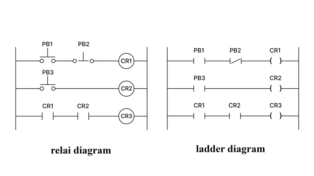
This design choice was brilliant: it allowed electricians to transition to computer-based control without needing to learn complex programming concepts. Instead of rewiring physical relays when process changes were needed, technicians could simply reprogram the PLC a revolutionary concept at the time.
How Ladder Logic Implements Basic Logic Functions
One of ladder logic’s most powerful aspects is how it implements fundamental digital logic operations:
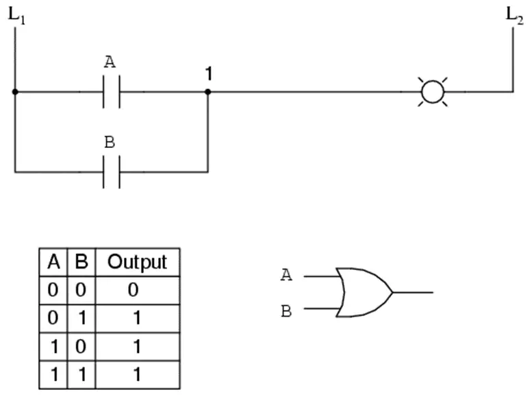
- OR Logic: Created by placing contacts in parallel on a rung. The output activates if any input is active.
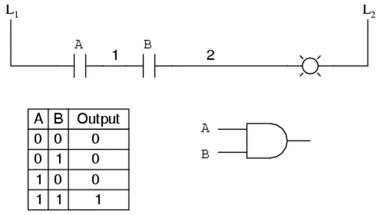
- AND Logic: Created by placing contacts in series on a rung. The output activates only when all inputs are active.
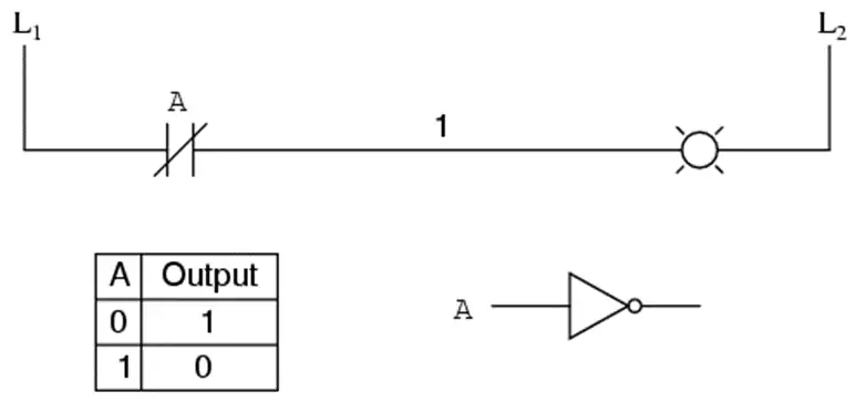
- NOT Logic: Implemented using normally-closed contacts instead of normally-open ones.
These basic building blocks can be combined to create more complex logic functions like NAND, NOR, and XOR gates. For example, an Exclusive-OR function requires two parallel branches with appropriately arranged normally-open and normally-closed contacts.
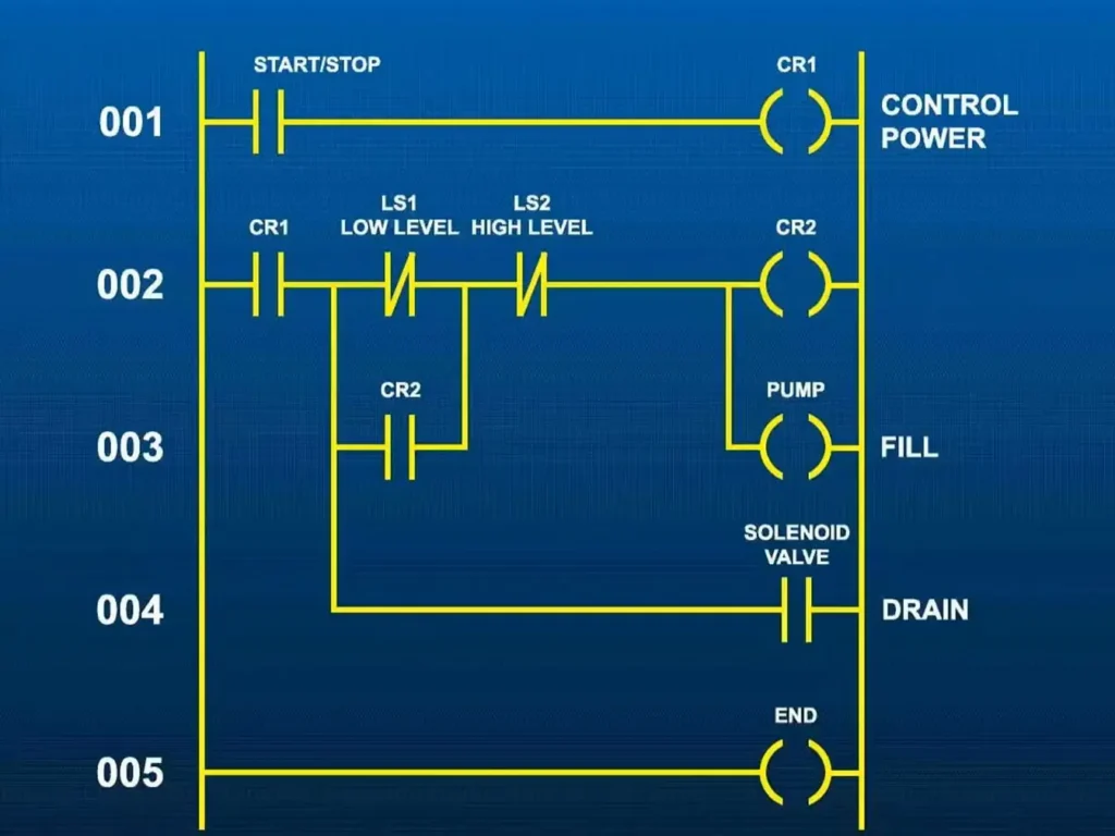
Practical Applications: Motor Control and Safety Systems
Ladder logic shines in real-world applications like motor control systems. Consider a reversible motor circuit where we need to prevent both forward and reverse contactors from energizing simultaneously a condition that would cause a dangerous short circuit.
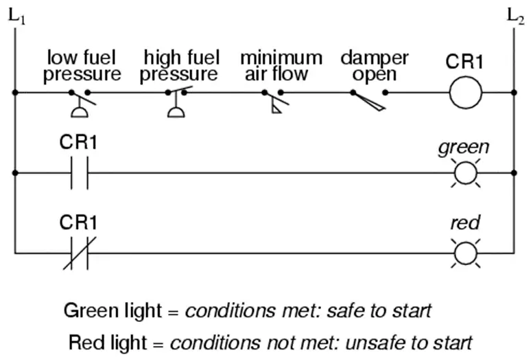
This is achieved through interlocking using auxiliary contacts on each contactor to prevent the other from energizing. Similarly, permissive circuits ensure multiple safety conditions are met before equipment can start .
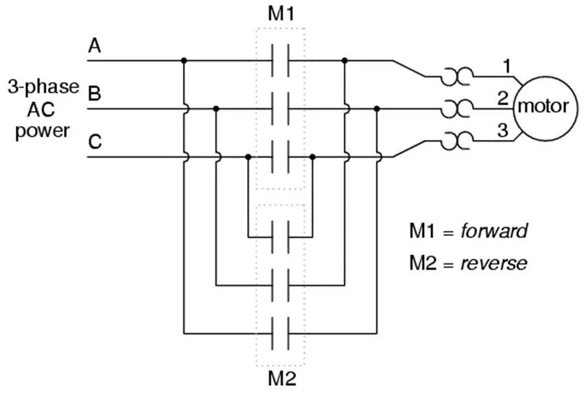
When contactor M1 is energized, the 3 phases (A, B, and C) are connected directly to terminals 1, 2, and 3 of the motor, respectively. However, when contactor M2 is energized, phases A and B are reversed, A going to motor terminal 2 and B going to motor terminal 1. This reversal of phase wires results in the motor spinning the opposite direction. Let’s examine the control circuit for these two contactors:
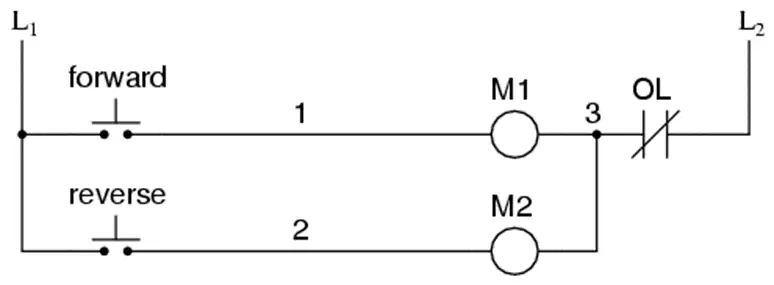
Take note of the normally-closed “OL” contact, which is the thermal overload contact activated by the “heater” elements wired in series with each phase of the AC motor. If the heaters get too hot, the contact will change from its normal (closed) state to being open, which will prevent either contactor from energizing.
To prevent this occurrence from happening, we can design the circuit so that the energization of one contactor prevents the energization of the other. This is called interlocking, and it is accomplished through the use of auxiliary contacts on each contactor, as such:
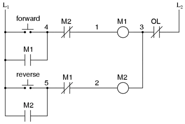
Now, when M1 is energized, the normally-closed auxiliary contact on the second rung will be open, thus preventing M2 from being energized, even if the “Reverse” pushbutton is actuated. Likewise, M1‘s energization is prevented when M2 is energized. Note, as well, how additional wire numbers (4 and 5) were added to reflect the wiring changes.
Fail-Safe Design: The Critical Safety Principle
Perhaps the most important concept in industrial control is fail-safe design. Since wiring failures (particularly “open” circuits) are statistically more common than other failures, control systems should default to the safest state when failures occur.
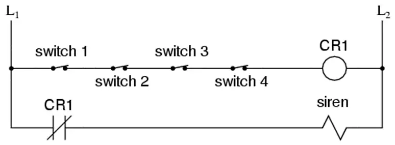
For example, in a fire alarm system, the circuit should be designed so that a broken wire causes a false alarm (annoying but safe) rather than a silent failure where the alarm doesn’t work when needed. This often means using normally-closed contacts in series rather than normally-open contacts in parallel.
Why Ladder Logic Endures in the Digital Age
Despite the availability of more modern programming languages (like Structured Text and Function Block Diagram), ladder logic remains dominant for several compelling reasons:
- Familiarity: Generations of technicians have been trained on ladder logic
- Visual troubleshooting: Problems can often be diagnosed by simply looking at the program
- Intuitive representation: The layout mirrors the electrical circuits it controls
- Flexibility: Logic can be changed without rewiring physical components
- Robustness: Well-designed ladder logic executes reliably in demanding industrial environments
Modern PLCs have evolved far beyond simple relay replacements they handle complex timing functions, data processing, and network communications. Yet they maintain the ladder logic interface that makes them accessible to the technicians who maintain them daily.
The Future of Ladder Logic
While newer programming paradigms continue to emerge, ladder logic shows no signs of disappearing. Its visual nature, intuitive representation of electrical logic, and the massive installed base of systems ensure its continued relevance. As industrial automation becomes increasingly connected through the Industrial Internet of Things (IIoT), ladder logic serves as the reliable foundation upon which more sophisticated control strategies are built.
In an era of rapidly evolving technology, ladder logic stands as a testament to the power of good design simple enough to be understood by technicians on the factory floor, yet powerful enough to control the most complex manufacturing processes. For anyone entering the field of industrial automation, understanding ladder logic isn’t just valuable it’s essential.


