
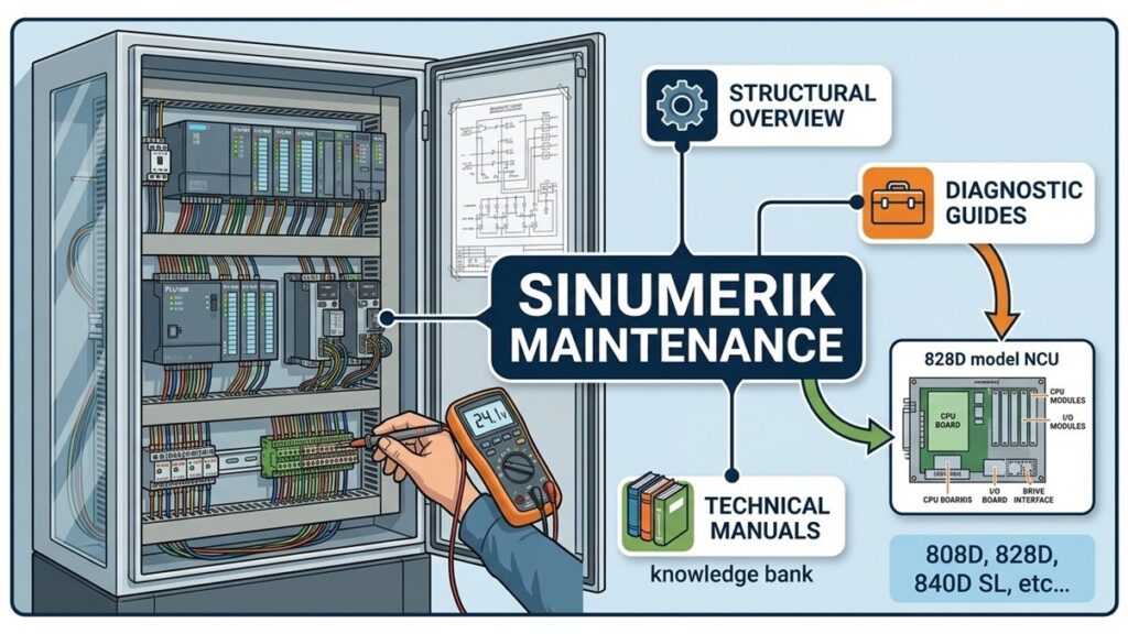
In the field of machine tool automation, the Siemens SINUMERIK 828D has established itself as the premier mid-range control solution for standardized milling, turning, and live-tooling applications. Engineered for high reliability and advanced precision on modern metal-cutting machinery, understanding its underlying hardware structure and diagnostic principles is crucial for electromechanical technicians and engineers aiming to minimize production downtime.
This guide breaks down the physical architecture of the SINUMERIK 828D and outlines practical preventive maintenance and troubleshooting strategies for the shop floor.
1. Hardware Architecture & System Layout
The SINUMERIK 828D features a compact, panel-based design where the CNC kernel, Human-Machine Interface (HMI), PLC, and motion control interfaces are tightly integrated into a single hardware assembly known as the PPU (Panel Processing Unit).
+-------------------------------------------------------------------+
|                        PPU (Panel Processing Unit)                |
|  - Integrated LCD Screen & Operator Keyboard (OP 010 / OP 010C)   |
|  - Embedded CNC Core (NCK) + Integrated S7-300 PLC Logic          |
|  - Interfaces: USB, Ethernet (PROFINET), DRIVE-CLiQ               |
+-------------------------------------------------------------------+
                                  |
            +---------------------+---------------------+
            | (PROFINET IRT / DRIVE-CLiQ Communication)  |
            v                                           v
+-----------------------+                   +-----------------------+
|   SINAMICS Drives     |                   |  I/O Modules (MCP)    |
|  (S120 Combi/Booksize)|                   |  Sensors / Actuators  |
+-----------------------+                   +-----------------------+
            |
            v
+-----------------------+
| SIMOTICS Motors &     |
| DRIVE-CLiQ Encoders   |
+-----------------------+
Key Hardware Components:
- PPU (Panel Processing Unit): Serves as the central processing brain. The 828D ships in two main variants: the PPU 240.3 (optimized for turning, supporting up to 4 feed axes and 2 spindles) and the PPU 260.3 (optimized for milling, supporting up to 5 feed axes and 1 spindle) . It houses the mainboard, NCK execution unit, and a 256 KB work memory PLC.
- Drives & Servomotors (SINAMICS S120): Typically paired with SINAMICS S120 Combi or Booksize drive systems and SIMOTICS servomotors. The 828D utilizes the proprietary DRIVE-CLiQ digital interface, meaning all axis feedback runs over a single cable, eliminating the need for separate analog encoder wiring to the NCK.
- I/O Subsystem & PROFINET: Digital and analog I/O are handled via PROFINET IRT (Isochronous Real-Time) or direct terminal wiring. This allows seamless integration of machine limit switches, tool changers, coolant pumps, and safety interlocks.
2. Preventive Maintenance & Diagnostic Workflow
To maintain high operational availability and prevent unexpected control failures on machines equipped with a SINUMERIK 828D, maintenance engineers should adhere to the following diagnostic protocols:
A. Data Backup Procedure (CNC/PLC/Drive Archives)
Always create a complete system archive prior to servicing, electrical panel modifications, or parameter adjustments:
- Insert a FAT32-formatted USB flash drive into one of the three front panel USB 2.0 ports.
- Navigate to System Data > Commissioning on the operator panel.
- Perform a full system export (NC/PLC/Drive Data Archive). This file is vital for restoring machine parameters in the event of memory corruption or PPU board replacement.
B. Status LED Diagnostics
Check the diagnostic LEDs located on the rear terminal side of the PPU and on the SINAMICS S120 drive units:
- RDY (Ready) – Solid Green: The PPU power supply is stable, initialization is complete, and system communication is healthy.
- RDY – Red or Flashing: Indicates an internal power rail fault, CNC kernel boot failure, or a hardware fault within the PPU or drive unit.
- LINK/ACT LEDs: On the X127 (service) and X130 (machine network) Ethernet ports, ensure steady/flashing green lights to confirm PROFINET IRT communication integrity.
C. 24 VDC Power Rail & Cable Integrity
Unexplained intermittent resets, encoder faults, or communication drops on the 828D are frequently linked to poor 24 VDC control power quality or compromised DRIVE-CLiQ shielding. Ensure that the incoming supply voltage at the PPU and drive power terminals remains strictly within 20.4 VDC to 28.8 VDC, even during inductive load switching (e.g., solenoid valves, magnetic contactors, or spindle brakes).
3. Troubleshooting Common System Alarms
| Alarm Code | Description | Probable Cause | Corrective Maintenance Action |
|---|---|---|---|
| 25050 | Axis %1 encoder error | DRIVE-CLiQ cable fault, loose connector, or motor encoder failure. | Check DRIVE-CLiQ topology in Diagnostics → Drive System; reseat X101–X105 connectors and inspect cable shielding. |
| 26000 | Drive DC link undervoltage | Input voltage drop (e.g., <480V) or line filter/reactor fault. | Measure L1/L2/L3 at the infeed module; check line reactor fuses and main contactor health. |
| 380500 | PLC user program: watchdog | PLC OB1 cycle time exceeded the 150 ms threshold. | Review ladder logic in STEP 7 / TIA Portal; check for infinite loops or excessive processing in FC/FB calls. |
| 10620 | Axis hardware limit switch | Axis reached hard physical limit or limit switch wiring fault. | Jog the axis in the opposite direction; verify MD36100/36110 (software limits) against physical switch positioning. |
| 200001 | Drive not ready | Drive-side fault or PROFINET communication drop. | Check the S120 drive alarm history via SINUMERIK Operate; verify PROFINET device names and IP addressing. |
Conclusion
The Siemens SINUMERIK 828D delivers a robust, high-performance architecture that reduces cabinet wiring complexity through its integrated DRIVE-CLiQ topology and simplifies mid-range maintenance. Maintaining a strict routine of regular USB archive backups, monitoring 24V power supply stability, and verifying PROFINET cable integrity will eliminate the vast majority of downtime risks on the factory floor.


