Computer Numerical Control (CNC) machines have revolutionized the manufacturing industry by automating machine tools through computers executing pre-programmed sequences of machine control commands. Among the various CNC control systems available, the Fanuc System 10M stands out as a reliable and widely used control system, particularly for milling operations. This blog post delves into the general structure of a CNC machine equipped with a Fanuc System 10M control, exploring its key components, functionalities, and how they integrate to deliver precision and efficiency in machining.
Overview of CNC Machines and Fanuc System 10M
CNC machines are automated milling devices that make industrial components without direct human assistance. They use coded instructions that are sent to an internal computer, allowing factories to fabricate parts accurately and quickly. The Fanuc System 10M is a CNC control system developed by FANUC Corporation, a Japanese company known for its automation products. The “10M” designation indicates that this system is designed primarily for milling machines, offering a range of features tailored to complex machining tasks.
1. Main Structural Components of a CNC Machine
A CNC machine, regardless of the control system, consists of several key structural components that work together to perform machining operations. These include:
a. Machine Frame and Base
The machine frame provides the structural support for all other components. It must be rigid and vibration-resistant to ensure accuracy during machining. Machine base & structural elements:
- Cast-iron or polymer-concrete bed, column, saddle, table
- Hardened & ground box or linear ways (with Turcite / Ball-uff strips or rolling element rails)
- Way covers, telescopic guards, chip management tunnels
- The base houses the coolant system
- The electrical cabinet.
b. Spindle Assembly
The spindle is the heart of the machine, responsible for rotating the cutting tool. It is driven by a motor and can vary in speed and torque depending on the material being machined. The spindle’s precision directly affects the quality of the finished part.
Main spindle module:
- AC vector spindle motor (often Fanuc α/αi series)
- Spindle bearings, cartridge, draw-bar, Belleville/spring stack for tool clamping
- Spindle orientation (position coder or magnetic pickup) for tool change
- Spindle chiller or liquid cooling loop (on higher-power heads)
c. Axes and Drive System
CNC machines operate along multiple axes typically X, Y, and Z for 3-axis machines, with additional rotational axes (A, B, C) for more complex machines. Each axis is driven by servo motors controlled by the CNC system, ensuring precise movement and positioning.
Axes drive train (3-axis example):
- Fanuc α/αM or early β series AC servomotors, one per axis
- Couplings, timing belts or direct couplings
- Precision ball-screws (normally double-nut pre-loaded, 32–40 mm Ø)
- Linear scales or rotary encoders (closed-loop option)
- Way lubrication metering units (timed lube pump)
d. Tool Magazine and Changer
For automated operations, CNC machines are equipped with a tool magazine that holds multiple cutting tools. The tool changer automatically swaps tools as needed during the machining process, reducing downtime and increasing productivity.
Automatic tool changer (machining center):
- Swing-arm, umbrella or drum magazine, 16–40 tools typical
- Tool-count and tool-pot position encoder
- Cam-type or servo-driven arm with Fanuc I/O interface
- Tool-pot up/down and clamp/unclamp cylinders (24 VDC solenoids)
e. Worktable
The worktable holds the workpiece in place during machining. It may include fixtures or clamps to secure the material. Some tables are rotary or tilting, allowing for multi-sided machining.
Work support & fixtures
- T-slotted table or pallet receiver (Matsuura, Kitagawa, etc.)
- Hydraulic or pneumatic clamp circuits, controlled by 10M M-codes via I/O module
- Pallet-change shuttle (if machine is a “hori-cell” type)
f. Electrical cabinet (door interlocked)
- Fanuc 10M main CPU rack (slots for axis, I/O, spindle, memory, HSSB)
- Axis servo amplifiers (A06B-6057/6058 or αSVU)
- Spindle amplifier module (A06B-6059/6078 or αSPx)
- 24 VDC logic supply & 200/380 VAC servo mains contactor chain
- E-stop chain, thermal overloads, CE/UL relays
- I/O unit Model A or B (96/64 points typical) for relays, solenoids, sensors
- Remote I/O blocks near ATC and pallet to cut wiring
g. Coolant & chip system
- Flood coolant pump (½–3 hp)
- Through-spindle coolant option (20–70 bar) with rotary union
- Chip auger or scraper conveyor, lift-up chip drum
- Coolant chiller / refractometer tank
h. Way & ball-screw lubrication
- Bijur, Lincoln or Fanuc-labeled progressive block system
- Oil-level float switches wired to 10M PLC alarms
i. Pneumatic stack
- 5–7 bar FRL unit, spindle air blast, tool-unclamp, pallet clamp, way-guard seals
- Pressure switches monitored by 10M inputs
2. Fanuc System 10M Control Overview
The Fanuc System 10M is a modular CNC control system designed for milling machines. Introduced in the 1980’s, it was part of Fanuc’s 10 series, which included both 10M (for milling) and 10T (for turning) variants. Despite being an older system, it remains in use in many shops due to its durability and reliability.
Key Features of the Fanuc 10M:
- Multi-axis control: Supports up to 5 axes simultaneously.
- Macro programming: Allows for advanced programming techniques.
- Custom macros and subprograms: Enhances flexibility.
- CRT/MDI panel: Provides a user interface for programming and operation.
- RS-232 communication: Enables DNC (Direct Numerical Control) operations.
3. Control Unit Architecture
The Fanuc System 10M control unit is composed of several modules that handle different aspects of machine control. These include:
a. Central Processing Unit (CPU)
The CPU is the brain of the control system. It processes the part program, interprets commands, and coordinates the movement of the machine axes. It also handles logic operations, calculations, and communication with peripheral devices.
b. Axis Control Cards
Each axis of the machine has a dedicated control card that manages the servo motor for that axis. These cards receive commands from the CPU and translate them into precise motor movements. Feedback devices like encoders or resolvers provide position data to ensure accuracy.
c. I/O Interface
The Input / Output interface connects the CNC control to external devices such as limit switches, sensors, coolant systems, and spindle drives. It allows the CNC system to monitor machine status and control auxiliary functions.
Communications / DNC:
- RS-232-C port (JD5A) on 10M CPU for drip-feed or program upload
- Optional HSSB (High-Speed Serial Bus) to a PC front-end or FAPT-CAM
d. Memory Module
The memory module stores part programs, tool offsets, parameters, and system settings. The Fanuc 10M supports both RAM and bubble memory, with options for expansion via cassette or floppy disk interfaces.
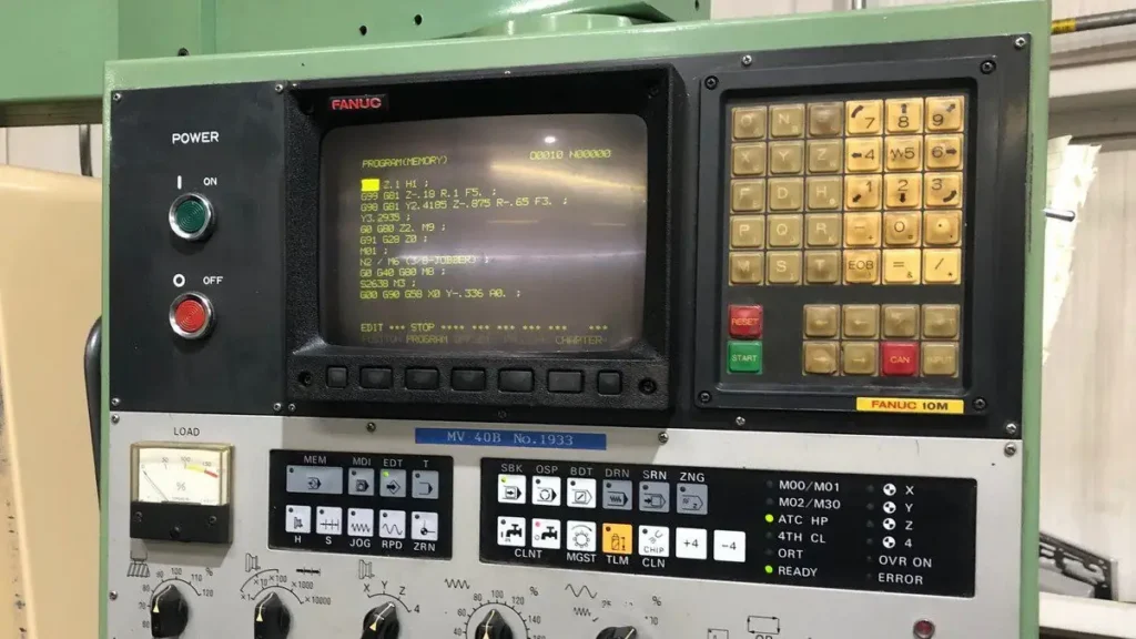
e. CRT/MDI Unit
The CRT (Cathode Ray Tube) display and MDI (Manual Data Input) panel allow operators to interact with the CNC system. The display shows program code, machine status, alarms, and diagnostic information. The MDI keypad is used for manual programming, editing, and data entry.
Operator station
- 10M monochrome or 14″ color CRT/MDI unit (A02B-0098-C041)
- Machine panel with Fanuc matrix key membrane (EDIT, AUTO, MDI, HANDLE, MPG )
- Electronic hand-wheel (MPG) on pendant
- USB/PCMCIA or old bubble-memory cassette port on side of CRT
4. Servo System and Feedback Mechanisms
The servo system is responsible for the precise movement of the machine axes. In a Fanuc 10M-controlled machine, this system includes:
a. Servo Motors
These are high-performance electric motors that drive the axes. They are capable of rapid acceleration and deceleration, as well as holding position under load.
b. Servo Amplifiers
Amplifiers provide the necessary power to the servo motors based on control signals from the axis control cards. They also monitor motor performance and provide feedback to the CNC system.
c. Feedback Devices
Encoders or resolvers attached to the servo motors and ball screws provide real-time position and velocity feedback. This closed-loop system ensures that the actual position of the axis matches the commanded position.
5. Spindle Control
The spindle is controlled independently of the axes but is still integrated into the Fanuc 10M system. Key aspects include:
a. Spindle Drive Unit
This unit controls the speed and direction of the spindle motor. It receives commands from the CNC system and adjusts the motor accordingly.
b. Spindle Orientation
For operations like tapping or tool changes, the spindle must be oriented to a specific position. The Fanuc 10M supports spindle orientation through the use of sensors and the spindle drive unit.
c. Gear Selection
Some machines have multiple spindle speed ranges achieved through mechanical gearing. The CNC system can select the appropriate gear ratio based on the required speed and torque.
6. Tool Management System
Efficient tool management is critical for automated machining. The Fanuc 10M supports:
a. Tool Offset Memory
Each tool has associated geometry and wear offsets stored in the control memory. These offsets compensate for tool length, diameter, and wear, ensuring accurate machining.
b. Tool Life Management
The system can track tool usage and alert the operator when a tool reaches its life limit. This helps prevent tool breakage and maintain part quality.
c. Automatic Tool Changer (ATC) Interface
The Fanuc 10M interfaces with the machine’s ATC to manage tool changes. It ensures the correct tool is selected and properly positioned before resuming machining.
7. Programming and Operation
Programming a Fanuc 10M-controlled machine involves creating a part program using G-code and M-code. The system supports:
a. Standard G-Codes
These include commands for linear interpolation (G01), rapid positioning (G00), circular interpolation (G02/G03), and more.
b. Canned Cycles
Pre-defined cycles for common operations like drilling, tapping, and boring simplify programming and reduce code length.
c. Custom Macros
Advanced users can write macro programs using variables, conditional statements, and loops to automate complex tasks.
d. DNC Operation
For large programs, the Fanuc 10M supports DNC mode, allowing the machine to run programs directly from an external computer via RS-232.
8. Maintenance and Diagnostics
The Fanuc System 10M includes built-in diagnostics to help troubleshoot issues. These include:
a. Alarm System
The system displays alarms for errors such as servo faults, program mistakes, or hardware failures. Each alarm has a specific code and description.
b. Parameter Settings
Hundreds of parameters control machine behavior. These can be adjusted to optimize performance or accommodate different hardware configurations.
c. Backup and Restore
Programs and parameters can be backed up to external storage devices, ensuring data is not lost in case of memory failure.
9. Documentation normally shipped with the machine
- Fanuc 10M Operator’s Manual (B-54204E)
- Fanuc 10M Maintenance Manual (B-54194E)
- Ladder diagram print-out (PCMCIA or paper)
- Machine builder’s mechanical assembly, ATC timing chart, spare-parts list
Conclusion
The Fanuc System 10M is a robust and versatile CNC control system that has stood the test of time. When integrated into a CNC milling machine, it provides precise control over all aspects of the machining process from axis movement and spindle speed to tool management and program execution. Understanding the general structure of such a system is essential for operators, programmers, and maintenance personnel to maximize productivity and ensure reliable operation. While newer systems offer more advanced features, the Fanuc 10M remains a testament to durable engineering and effective CNC control design.
Final Thoughts
Whether you’re maintaining legacy equipment or exploring the evolution of CNC technology, the Fanuc System 10M offers valuable insights into the foundational principles of CNC machining. Its modular design, reliable performance, and comprehensive functionality make it a cornerstone in the history of industrial automation.


